
How to Use BMA180: Examples, Pinouts, and Specs
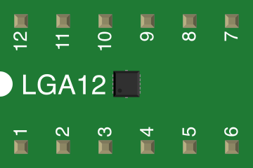
 Design with BMA180 in Cirkit Designer
Introduction
The BMA180 is a high-performance, low-power 3-axis accelerometer designed for motion sensing applications. It offers precise measurement of acceleration in three axes (X, Y, Z) and is widely used in mobile devices, wearables, and IoT applications. With its compact size and low power consumption, the BMA180 is ideal for detecting orientation, tilt, and motion in battery-powered devices.
Explore Projects Built with BMA180
 Open Project in Cirkit Designer
 Open Project in Cirkit Designer
 Open Project in Cirkit Designer
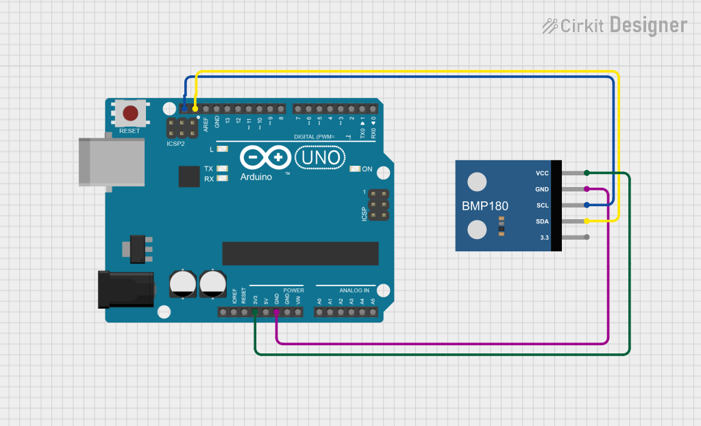 Open Project in Cirkit Designer
Explore Projects Built with BMA180
Open Project in Cirkit DesignerOpen Project in Cirkit DesignerOpen Project in Cirkit DesignerOpen Project in Cirkit DesignerCommon Applications
- Mobile devices for screen orientation and motion detection
- Wearable devices for fitness tracking and activity monitoring
- IoT devices for vibration analysis and motion-triggered events
- Robotics for navigation and stabilization
- Gaming controllers for motion-based input
Technical Specifications
The BMA180 offers a range of features and specifications that make it suitable for various applications. Below are the key technical details:
Key Specifications
- Supply Voltage: 1.8V to 3.6V
- Current Consumption: 650 µA (typical in normal mode), 5 µA (in sleep mode)
- Measurement Range: ±1g, ±1.5g, ±2g, ±3g, ±4g, ±8g, ±16g (configurable)
- Output Data Rate: Up to 1200 Hz
- Interface: I²C and SPI (selectable)
- Operating Temperature: -40°C to +85°C
- Sensitivity: Configurable based on measurement range
- Package: LGA-16 (3mm x 3mm x 0.9mm)
Pin Configuration and Descriptions
The BMA180 comes in a 16-pin LGA package. Below is the pin configuration:
| Pin Number | Pin Name | Description |
|---|---|---|
| 1 | VDD | Power supply (1.8V to 3.6V) |
| 2 | GND | Ground |
| 3 | SCL/SPC | I²C clock / SPI clock |
| 4 | SDA/SDI/SDO | I²C data / SPI data input/output |
| 5 | CSB | Chip select for SPI (active low) |
| 6 | INT1 | Interrupt 1 output |
| 7 | INT2 | Interrupt 2 output |
| 8 | NC | Not connected (leave unconnected) |
| 9-16 | NC | Not connected (leave unconnected) |
Usage Instructions
The BMA180 can be integrated into a circuit using either the I²C or SPI interface. Below are the steps and considerations for using the BMA180:
Circuit Connection
- Power Supply: Connect the VDD pin to a 1.8V to 3.6V power source and the GND pin to ground.
- Communication Interface:
- For I²C: Connect the SCL pin to the I²C clock line and the SDA pin to the I²C data line. Pull-up resistors (typically 4.7kΩ) are required on both lines.
- For SPI: Connect the SPC pin to the SPI clock, the SDI/SDO pin to the SPI data line, and the CSB pin to the SPI chip select line.
- Interrupts: If needed, connect INT1 and/or INT2 to microcontroller GPIO pins to handle motion-triggered interrupts.
Configuration and Initialization
- The BMA180 requires initialization after power-up. This includes setting the measurement range, output data rate, and enabling the desired interface (I²C or SPI).
- Below is an example of how to configure the BMA180 using an Arduino UNO via I²C:
#include <Wire.h> // Include the Wire library for I²C communication

#define BMA180_ADDRESS 0x40 // Default I²C address of the BMA180
#define CTRL_REG 0x0D       // Control register address
#define RANGE_REG 0x35      // Range register address

void setup() {
  Wire.begin(); // Initialize I²C communication
  Serial.begin(9600); // Initialize serial communication for debugging

  // Configure the BMA180
  Wire.beginTransmission(BMA180_ADDRESS);
  Wire.write(CTRL_REG); // Select the control register
  Wire.write(0x10);     // Set the device to normal mode
  Wire.endTransmission();

  Wire.beginTransmission(BMA180_ADDRESS);
  Wire.write(RANGE_REG); // Select the range register
  Wire.write(0x04);      // Set measurement range to ±2g
  Wire.endTransmission();

  Serial.println("BMA180 initialized");
}

void loop() {
  // Read acceleration data (example for X-axis)
  Wire.beginTransmission(BMA180_ADDRESS);
  Wire.write(0x02); // Address of the X-axis LSB register
  Wire.endTransmission();
  Wire.requestFrom(BMA180_ADDRESS, 2); // Request 2 bytes (LSB + MSB)

  if (Wire.available() == 2) {
    int16_t xAccel = Wire.read(); // Read LSB
    xAccel |= (Wire.read() << 8); // Read MSB and combine
    Serial.print("X-Axis Acceleration: ");
    Serial.println(xAccel);
  }

  delay(500); // Delay for readability
}
Best Practices
- Use decoupling capacitors (e.g., 0.1µF) near the VDD pin to reduce noise.
- Ensure proper pull-up resistors are used for I²C communication.
- Avoid exposing the sensor to extreme temperatures or mechanical stress.
Troubleshooting and FAQs
Common Issues
No Communication with the Sensor:
- Ensure the correct I²C address (default: 0x40) is used.
- Verify pull-up resistors are connected on the I²C lines.
- Check for loose or incorrect wiring.
Incorrect or No Acceleration Data:
- Confirm the sensor is properly initialized (e.g., measurement range and mode).
- Verify the data registers are being read correctly.
High Noise in Readings:
- Ensure the sensor is mounted securely to avoid vibrations.
- Use filtering techniques (e.g., averaging multiple readings) to reduce noise.
FAQs
Q: Can the BMA180 operate at 5V?
A: No, the BMA180 operates within a supply voltage range of 1.8V to 3.6V. Using 5V may damage the sensor.
Q: How do I switch between I²C and SPI modes?
A: The communication mode is determined by the state of the CSB pin. Pull CSB high for I²C mode and low for SPI mode.
Q: What is the maximum measurement range of the BMA180?
A: The BMA180 supports a maximum measurement range of ±16g, which can be configured via the range register.
Q: Can I use the BMA180 for free-fall detection?
A: Yes, the BMA180 supports free-fall detection and other motion-triggered interrupts, which can be configured using its interrupt registers.
By following this documentation, you can effectively integrate and use the BMA180 in your projects.