How to Use 6 Channel DIN Fused DC Distribution: Examples, Pinouts, and Specs
Introduction
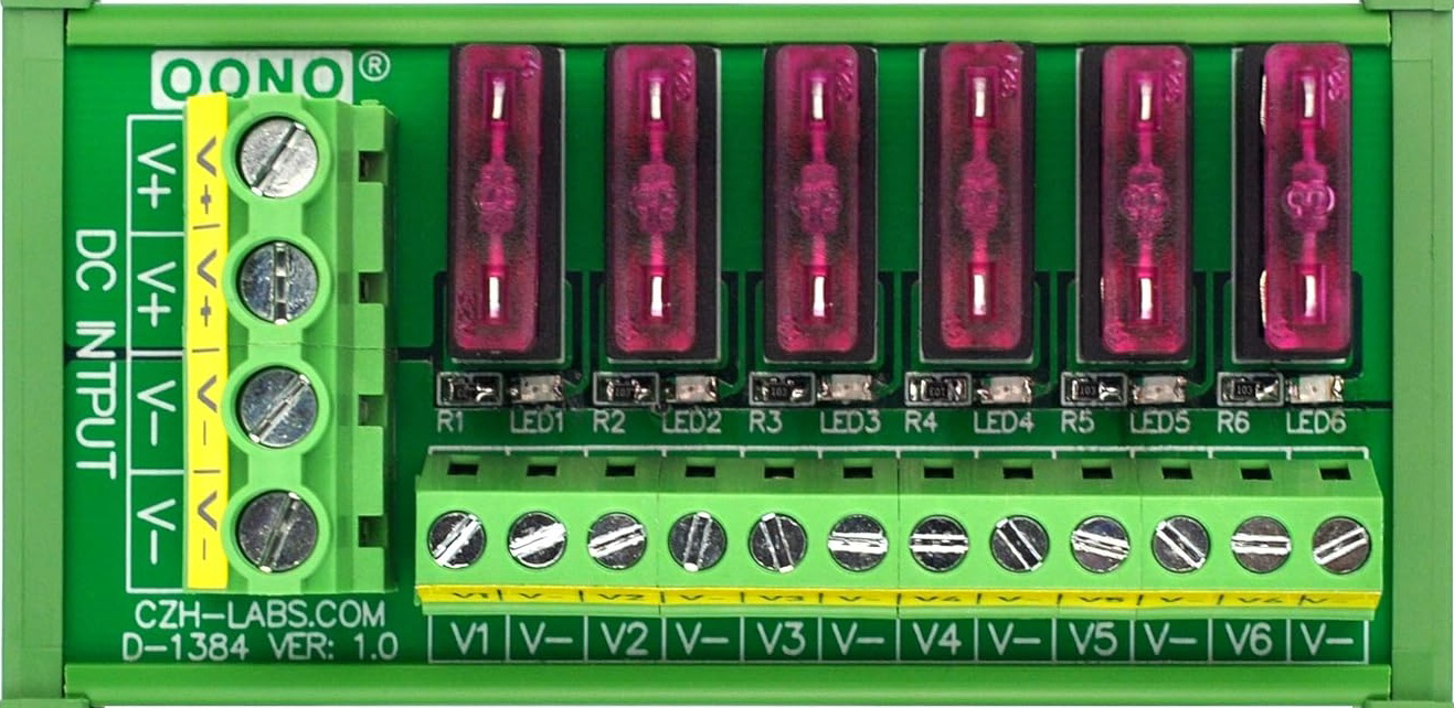
The 6 Channel DIN Fused DC Distribution unit is a versatile and reliable component designed to manage and distribute DC power across six independent channels. Each channel is equipped with a built-in fuse to provide overcurrent protection, ensuring the safety and longevity of connected devices. This unit is typically mounted on a DIN rail, making it ideal for use in industrial control panels, automation systems, and other electrical installations requiring organized and protected DC power distribution.
Explore Projects Built with 6 Channel DIN Fused DC Distribution


Explore Projects Built with 6 Channel DIN Fused DC Distribution
Common Applications and Use Cases
- Industrial automation systems
- Power distribution in control panels
- Renewable energy systems (e.g., solar power installations)
- Telecommunications equipment
- Low-voltage DC lighting systems
- Any application requiring organized and fused DC power distribution
Technical Specifications
The following table outlines the key technical details of the 6 Channel DIN Fused DC Distribution unit:
| Parameter | Specification |
|---|---|
| Input Voltage Range | 12V DC to 48V DC |
| Maximum Current per Channel | 10A |
| Total Maximum Current | 60A (shared across all channels) |
| Fuse Type | Standard blade fuses (e.g., ATC/ATO) |
| Fuse Rating per Channel | User-replaceable, up to 10A |
| Mounting Type | DIN rail (35mm standard) |
| Operating Temperature Range | -20°C to +70°C |
| Dimensions (L x W x H) | 100mm x 80mm x 60mm |
| Weight | 250g |
Pin Configuration and Descriptions
The unit features screw terminals for input and output connections. The pin configuration is as follows:
| Terminal | Description |
|---|---|
| Input (+) | Positive DC input terminal |
| Input (-) | Negative DC input terminal (ground) |
| Output 1 (+) | Positive output for Channel 1 |
| Output 1 (-) | Negative output for Channel 1 (shared ground) |
| Output 2 (+) | Positive output for Channel 2 |
| Output 2 (-) | Negative output for Channel 2 (shared ground) |
| Output 3 (+) | Positive output for Channel 3 |
| Output 3 (-) | Negative output for Channel 3 (shared ground) |
| Output 4 (+) | Positive output for Channel 4 |
| Output 4 (-) | Negative output for Channel 4 (shared ground) |
| Output 5 (+) | Positive output for Channel 5 |
| Output 5 (-) | Negative output for Channel 5 (shared ground) |
| Output 6 (+) | Positive output for Channel 6 |
| Output 6 (-) | Negative output for Channel 6 (shared ground) |
Usage Instructions
How to Use the Component in a Circuit
- Mounting the Unit: Securely attach the unit to a 35mm DIN rail in your electrical panel.
- Connecting the Input:
- Connect the positive DC supply to the
Input (+)terminal. - Connect the negative DC supply (ground) to the
Input (-)terminal.
- Connect the positive DC supply to the
- Connecting the Outputs:
- For each device or circuit, connect the positive wire to the corresponding
Output (+)terminal (e.g.,Output 1 (+)for Channel 1). - Connect the negative wire to the corresponding
Output (-)terminal (shared ground).
- For each device or circuit, connect the positive wire to the corresponding
- Fuse Installation:
- Insert the appropriate blade fuse (up to 10A) into the fuse holder for each channel.
- Ensure the fuse rating matches the current requirements of the connected device.
- Power On:
- After verifying all connections, power on the DC supply. The unit will distribute power to the connected devices.
Important Considerations and Best Practices
- Fuse Selection: Always use fuses with a rating slightly higher than the normal operating current of the connected device but below the maximum channel rating (10A).
- Wire Gauge: Use appropriately rated wires for the input and output connections to handle the expected current without overheating.
- Overcurrent Protection: The built-in fuses provide overcurrent protection, but additional circuit breakers or protection devices may be required for the input supply.
- Ventilation: Ensure adequate ventilation around the unit to prevent overheating, especially in high-current applications.
- Polarity: Double-check the polarity of all connections to avoid damage to the unit or connected devices.
Example: Connecting to an Arduino UNO
The 6 Channel DIN Fused DC Distribution unit can be used to power an Arduino UNO and other peripherals. Below is an example of how to connect the unit:
- Connect a 12V DC power supply to the
Input (+)andInput (-)terminals. - Insert a 1A fuse into the fuse holder for Channel 1.
- Connect the
Output 1 (+)terminal to the VIN pin of the Arduino UNO. - Connect the
Output 1 (-)terminal to the GND pin of the Arduino UNO.
Here is a simple Arduino sketch to blink an LED connected to the Arduino:
// This sketch blinks an LED connected to pin 13 of the Arduino UNO.
// Ensure the Arduino is powered via the 6 Channel DIN Fused DC Distribution unit.

void setup() {
  pinMode(13, OUTPUT); // Set pin 13 as an output
}

void loop() {
  digitalWrite(13, HIGH); // Turn the LED on
  delay(1000);            // Wait for 1 second
  digitalWrite(13, LOW);  // Turn the LED off
  delay(1000);            // Wait for 1 second
}
Troubleshooting and FAQs
Common Issues and Solutions
No Power to Outputs:
- Cause: Blown fuse or incorrect input connection.
- Solution: Check and replace the fuse for the affected channel. Verify the input connections.
Overheating:
- Cause: Exceeding the maximum current rating or poor ventilation.
- Solution: Reduce the load on the channels and ensure proper ventilation around the unit.
Device Not Powering On:
- Cause: Incorrect polarity or insufficient fuse rating.
- Solution: Verify the polarity of the connections and ensure the fuse rating matches the device's current requirements.
Fuse Blowing Frequently:
- Cause: Overcurrent or short circuit in the connected device.
- Solution: Inspect the connected device for faults and ensure the current draw does not exceed the fuse rating.
FAQs
Q: Can I use this unit with an AC power supply?
A: No, this unit is designed for DC power only. Using an AC supply may damage the unit and connected devices.
Q: What type of fuses should I use?
A: Use standard blade fuses (e.g., ATC/ATO) with a rating appropriate for the connected device, up to 10A per channel.
Q: Can I connect multiple devices to a single channel?
A: Yes, but ensure the total current draw does not exceed the channel's fuse rating or the wire's capacity.
Q: Is the unit waterproof?
A: No, the unit is not waterproof. It should be installed in a dry, protected environment.