How to Use ESP32-S3 DevKit-C: Examples, Pinouts, and Specs
Introduction
The ESP32-S3 DevKit-C is a development board manufactured by YK, featuring the powerful ESP32-S3 chip. This board is designed for IoT (Internet of Things) applications, offering integrated Wi-Fi and Bluetooth connectivity. It is ideal for prototyping and developing smart devices, thanks to its versatile GPIO pins and support for various peripherals.
Explore Projects Built with ESP32-S3 DevKit-C


Explore Projects Built with ESP32-S3 DevKit-C
Common Applications
- Smart home devices
- Wearable electronics
- Industrial IoT systems
- Wireless sensor networks
- Robotics and automation
- Edge computing and AI applications
Technical Specifications
The ESP32-S3 DevKit-C is built around the ESP32-S3 chip, which is optimized for low-power and high-performance applications. Below are the key technical details:
Key Features
- Processor: Dual-core Xtensa LX7 CPU, up to 240 MHz
- Wireless Connectivity:
- Wi-Fi: 802.11 b/g/n (2.4 GHz)
- Bluetooth: Bluetooth 5.0 (LE)
- Memory:
- 512 KB SRAM
- 8 MB PSRAM (external)
- Flash Storage: 16 MB
- GPIO Pins: 21 (configurable for various peripherals)
- Operating Voltage: 3.3V
- Power Supply: USB Type-C (5V input)
- Interfaces: SPI, I2C, UART, ADC, DAC, PWM
- USB-to-Serial Chip: CP2102N
- Dimensions: 54 mm x 25 mm
Pin Configuration
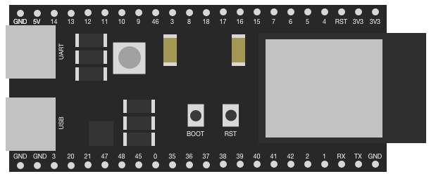
The ESP32-S3 DevKit-C features a 2x19 pin header layout. Below is the pin configuration:
| Pin Name | Description |
|---|---|
| 3V3 | 3.3V Power Output |
| GND | Ground |
| EN | Enable Pin (Active High) |
| IO0 | GPIO0, Boot Mode Selection |
| IO1 | GPIO1, UART TX |
| IO2 | GPIO2, General Purpose GPIO |
| IO3 | GPIO3, UART RX |
| IO4 | GPIO4, PWM/ADC Capable GPIO |
| IO5 | GPIO5, SPI SCK |
| IO12 | GPIO12, ADC/DAC Capable GPIO |
| IO13 | GPIO13, ADC/DAC Capable GPIO |
| IO14 | GPIO14, SPI MISO |
| IO15 | GPIO15, SPI MOSI |
| IO16 | GPIO16, I2C SDA |
| IO17 | GPIO17, I2C SCL |
| IO18 | GPIO18, PWM/ADC Capable GPIO |
| IO19 | GPIO19, PWM/ADC Capable GPIO |
| IO21 | GPIO21, General Purpose GPIO |
| IO22 | GPIO22, PWM/ADC Capable GPIO |
| IO23 | GPIO23, PWM/ADC Capable GPIO |
Note: Some GPIO pins have specific functions (e.g., ADC, DAC, SPI, I2C). Refer to the ESP32-S3 datasheet for detailed pin multiplexing options.
Usage Instructions
Using the ESP32-S3 DevKit-C in a Circuit
- Powering the Board: Connect the board to your computer or a USB power source using a USB Type-C cable. Ensure the power supply provides 5V.
- Programming the Board: Use the Arduino IDE or ESP-IDF (Espressif IoT Development Framework) to program the board. Install the necessary drivers for the CP2102N USB-to-Serial chip.
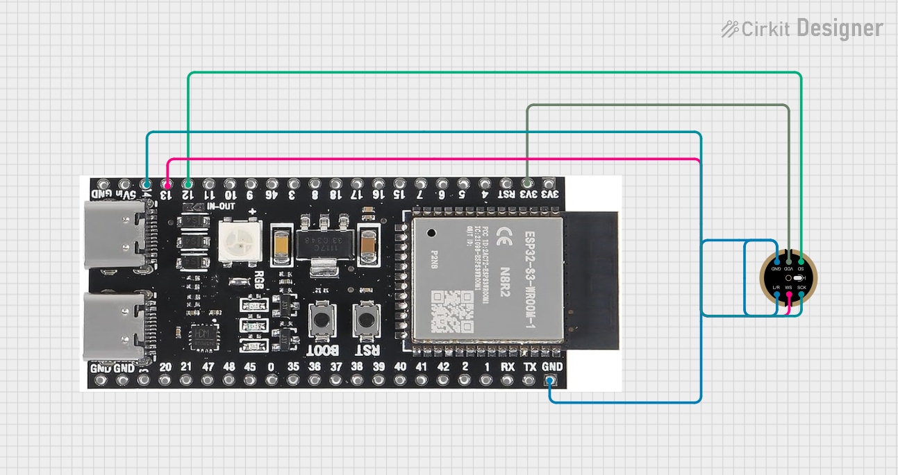
- Connecting Peripherals: Use the GPIO pins to connect sensors, actuators, or other peripherals. Ensure the voltage levels are compatible (3.3V logic).
- Flashing Firmware:
- Hold the BOOT button while pressing the EN button to enter flashing mode.
- Release the BOOT button and upload the firmware using your development environment.
Example: Blinking an LED with Arduino IDE
Below is an example of how to blink an LED connected to GPIO2:
// Define the GPIO pin where the LED is connected
#define LED_PIN 2

void setup() {
  // Set the LED pin as an output
  pinMode(LED_PIN, OUTPUT);
}

void loop() {
  // Turn the LED on
  digitalWrite(LED_PIN, HIGH);
  delay(1000); // Wait for 1 second

  // Turn the LED off
  digitalWrite(LED_PIN, LOW);
  delay(1000); // Wait for 1 second
}
Important Considerations
- Voltage Levels: The GPIO pins operate at 3.3V. Avoid connecting 5V peripherals directly to the pins without a level shifter.
- Power Supply: Ensure the USB power source can provide sufficient current (at least 500 mA) for the board and connected peripherals.
- Boot Mode: Use GPIO0 to select the boot mode. Pull it low to enter flashing mode.
Troubleshooting and FAQs
Common Issues
Board Not Detected by Computer
- Ensure the USB cable is functional and supports data transfer.
- Install the CP2102N USB-to-Serial driver if not already installed.
- Check the Device Manager (Windows) or
ls /dev/tty.*(macOS/Linux) for the serial port.
Failed to Upload Code
- Verify the correct board and port are selected in the Arduino IDE or ESP-IDF.
- Hold the BOOT button while pressing the EN button to enter flashing mode.
Wi-Fi Connection Issues
- Ensure the correct SSID and password are used in your code.
- Check for interference or weak signal strength.
GPIO Pin Not Working
- Verify the pin is not being used for another function (e.g., ADC, SPI).
- Check for wiring issues or incorrect pinMode configuration.
FAQs
Q: Can I power the board using an external 3.3V source?
A: Yes, you can power the board via the 3V3 pin, but ensure the source is stable and capable of supplying sufficient current.
Q: How do I reset the board?
A: Press the EN button to reset the board.
Q: Can I use the ESP32-S3 DevKit-C with MicroPython?
A: Yes, the board supports MicroPython. Flash the MicroPython firmware using tools like esptool.py.
Q: What is the maximum current draw of the board?
A: The board typically draws around 240 mA during Wi-Fi transmission. Ensure your power source can handle peak currents.
This concludes the documentation for the ESP32-S3 DevKit-C. For further details, refer to the official datasheet and user guide provided by the manufacturer.