
How to Use ENC28J60: Examples, Pinouts, and Specs
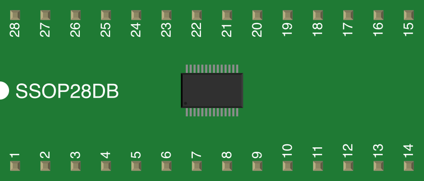
 Design with ENC28J60 in Cirkit Designer
Introduction
The ENC28J60 is a standalone Ethernet controller manufactured by Microchip Technology. It is designed to enable microcontrollers to connect to Ethernet networks via an SPI interface. The chip integrates both a Media Access Control (MAC) and Physical Layer (PHY) module, making it a compact and efficient solution for network communication in embedded systems.
Explore Projects Built with ENC28J60
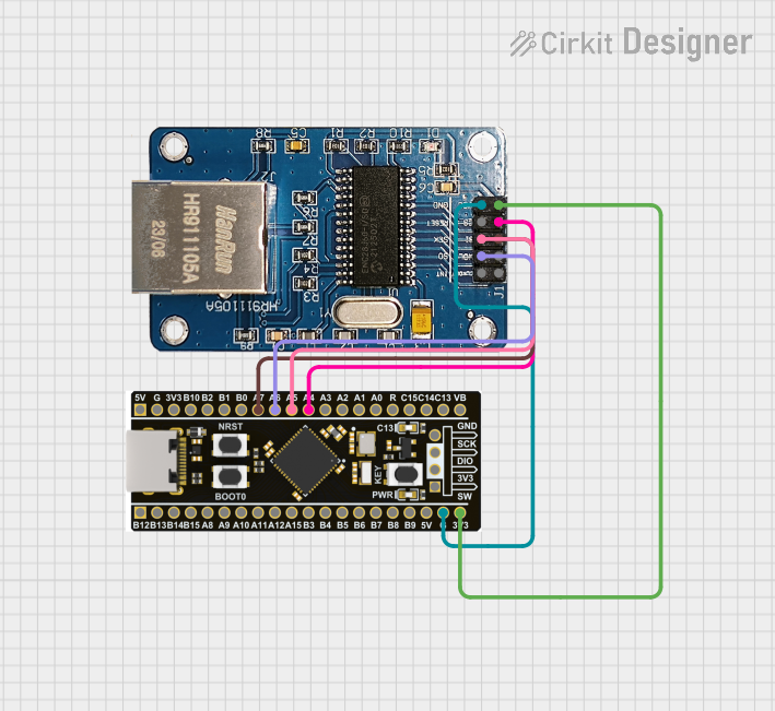 Open Project in Cirkit Designer
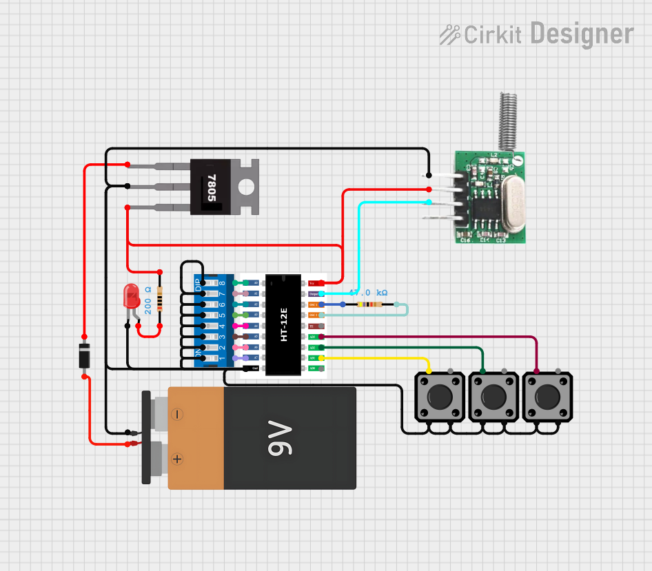 Open Project in Cirkit Designer
 Open Project in Cirkit Designer
 Open Project in Cirkit Designer
Explore Projects Built with ENC28J60
Open Project in Cirkit DesignerOpen Project in Cirkit DesignerOpen Project in Cirkit DesignerOpen Project in Cirkit DesignerCommon Applications and Use Cases
- Internet of Things (IoT) devices
- Home automation systems
- Industrial control systems
- Network-enabled sensors and actuators
- Remote monitoring and data logging
- Embedded web servers
The ENC28J60 is widely used in applications requiring low-cost Ethernet connectivity, especially in resource-constrained environments.
Technical Specifications
Key Technical Details
| Parameter | Value |
|---|---|
| Manufacturer | Microchip Technology |
| Part Number | ENC28J60 |
| Interface | SPI (Serial Peripheral Interface) |
| Operating Voltage | 3.3V |
| I/O Voltage Tolerance | 5V tolerant (on SPI and control pins) |
| Maximum SPI Clock Speed | 20 MHz |
| Ethernet Standards | IEEE 802.3 (10BASE-T) |
| MAC and PHY Integration | Yes |
| Buffer Memory | 8 KB (dual-port SRAM) |
| Operating Temperature | -40°C to +85°C |
| Package Types | SOIC, SSOP, QFN |
Pin Configuration and Descriptions
The ENC28J60 is typically available in a 28-pin package. Below is the pin configuration and description:
| Pin Number | Pin Name | Description |
|---|---|---|
| 1 | VSS | Ground connection |
| 2 | VDD | 3.3V power supply |
| 3 | CLKOUT | Programmable clock output |
| 4 | SO | SPI data output (MISO) |
| 5 | SI | SPI data input (MOSI) |
| 6 | SCK | SPI clock input |
| 7 | CS | Chip select input (active low) |
| 8 | RESET | Active-low reset input |
| 9 | INT | Interrupt output (active low) |
| 10 | WOL | Wake-on-LAN interrupt output |
| 11 | NC | No connection |
| 12-19 | TX+/TX-/RX+/RX- | Differential transmit and receive pairs for Ethernet communication |
| 20 | OSC1 | Oscillator input |
| 21 | OSC2 | Oscillator output |
| 22-28 | Various | Additional pins for power, ground, and Ethernet PHY connections |
Usage Instructions
How to Use the ENC28J60 in a Circuit
- Power Supply: Connect the ENC28J60 to a 3.3V power supply. Ensure proper decoupling capacitors are placed near the VDD and VSS pins to reduce noise.
- SPI Interface: Connect the SPI pins (SCK, SI, SO, and CS) to the corresponding SPI pins on your microcontroller. Ensure the SPI clock speed does not exceed 20 MHz.
- Ethernet Connection: Connect the TX+/TX- and RX+/RX- pins to an Ethernet transformer and RJ45 connector for network communication.
- Oscillator: Attach a 25 MHz crystal oscillator to the OSC1 and OSC2 pins for proper operation.
- Interrupts: Optionally, connect the INT pin to a microcontroller GPIO pin to handle interrupts for events like packet reception.
Important Considerations and Best Practices
- Voltage Levels: While the ENC28J60 operates at 3.3V, its SPI pins are 5V tolerant, making it compatible with 5V microcontrollers.
- Buffer Management: The 8 KB SRAM buffer is shared between transmit and receive operations. Efficient buffer management is crucial for optimal performance.
- PCB Layout: Ensure proper grounding and minimize noise on the Ethernet signal lines. Use differential pair routing for TX and RX lines.
- Driver Support: Use libraries like the Arduino EthernetENC library for easier integration with microcontrollers.
Example: Connecting ENC28J60 to Arduino UNO
Below is an example of how to connect the ENC28J60 to an Arduino UNO and use it to create a simple web server.
Wiring Diagram
| ENC28J60 Pin | Arduino UNO Pin |
|---|---|
| VDD | 3.3V |
| VSS | GND |
| SCK | D13 (SCK) |
| SI | D11 (MOSI) |
| SO | D12 (MISO) |
| CS | D10 (SS) |
| RESET | Reset Pin |
| INT | D2 |
Arduino Code Example
#include <UIPEthernet.h> // Library for ENC28J60 Ethernet module

// MAC address and IP address for the Ethernet module
byte mac[] = { 0xDE, 0xAD, 0xBE, 0xEF, 0xFE, 0xED };
IPAddress ip(192, 168, 1, 177);

// Create an Ethernet server on port 80
EthernetServer server(80);

void setup() {
  // Initialize serial communication for debugging
  Serial.begin(9600);
  while (!Serial) {
    ; // Wait for serial port to connect
  }

  // Start the Ethernet connection
  if (Ethernet.begin(mac) == 0) {
    Serial.println("Failed to configure Ethernet using DHCP");
    // Use static IP if DHCP fails
    Ethernet.begin(mac, ip);
  }

  // Start the server
  server.begin();
  Serial.print("Server is at ");
  Serial.println(Ethernet.localIP());
}

void loop() {
  // Listen for incoming clients
  EthernetClient client = server.available();
  if (client) {
    Serial.println("New client connected");
    // Wait until the client sends data
    while (client.connected()) {
      if (client.available()) {
        char c = client.read();
        Serial.write(c); // Echo data to serial monitor

        // Respond with a basic HTML page
        client.println("HTTP/1.1 200 OK");
        client.println("Content-Type: text/html");
        client.println("Connection: close");
        client.println();
        client.println("<!DOCTYPE HTML>");
        client.println("<html>");
        client.println("<h1>Hello from ENC28J60!</h1>");
        client.println("</html>");
        break;
      }
    }
    // Close the connection
    client.stop();
    Serial.println("Client disconnected");
  }
}
Troubleshooting and FAQs
Common Issues
No Ethernet Connection:
- Ensure the RJ45 connector and Ethernet cable are properly connected.
- Verify the TX+/TX- and RX+/RX- connections to the Ethernet transformer.
SPI Communication Fails:
- Check the SPI wiring between the ENC28J60 and the microcontroller.
- Ensure the SPI clock speed does not exceed 20 MHz.
Module Not Responding:
- Verify the power supply voltage is 3.3V.
- Check the RESET pin connection and ensure it is not held low.
Packet Loss or Poor Performance:
- Optimize buffer usage in your code.
- Ensure proper grounding and minimize noise on the PCB.
FAQs
Q: Can the ENC28J60 work with 5V microcontrollers?
A: Yes, the SPI pins are 5V tolerant, but the chip itself must be powered with 3.3V.
Q: What is the maximum Ethernet speed supported?
A: The ENC28J60 supports 10 Mbps (10BASE-T) Ethernet communication.
Q: Is there a library for Arduino compatibility?
A: Yes, the UIPEthernet library is commonly used for Arduino projects with the ENC28J60.
Q: Can I use the ENC28J60 for wireless communication?
A: No, the ENC28J60 is designed for wired Ethernet communication only.
This concludes the documentation for the ENC28J60 Ethernet controller.