How to Use ATMEGA328: Examples, Pinouts, and Specs

 Design with ATMEGA328 in Cirkit Designer
Introduction
The ATMEGA328 is a high-performance Microchip picoPower® 8-bit AVR® RISC-based microcontroller. This versatile microcontroller combines 32KB ISP flash memory with read-while-write capabilities, 1KB EEPROM, 2KB SRAM, 23 general-purpose I/O lines, 32 general-purpose working registers, three flexible timer/counters with compare modes, internal and external interrupts, serial programmable USART, a byte-oriented 2-wire serial interface, SPI serial port, a 6-channel 10-bit A/D converter (8 channels in TQFP and QFN/MLF packages), programmable watchdog timer with internal oscillator, and five software-selectable power-saving modes. It is commonly used in Arduino Uno and other Arduino boards, making it a staple in both hobbyist and professional projects.
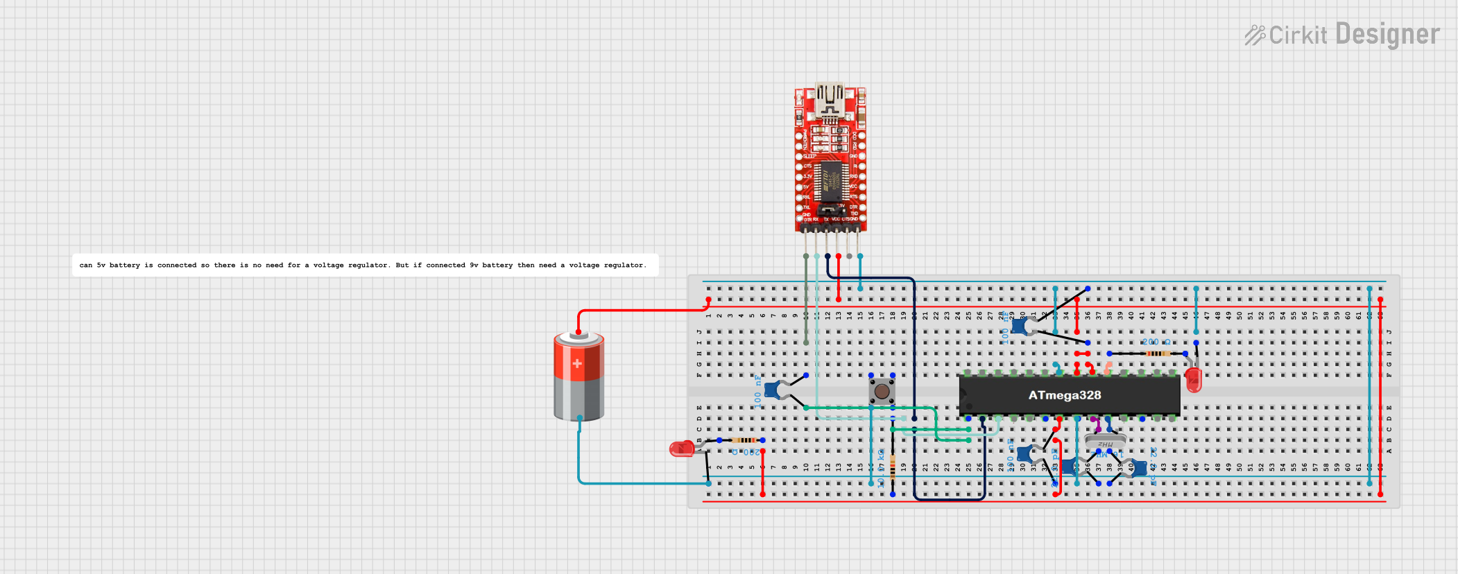
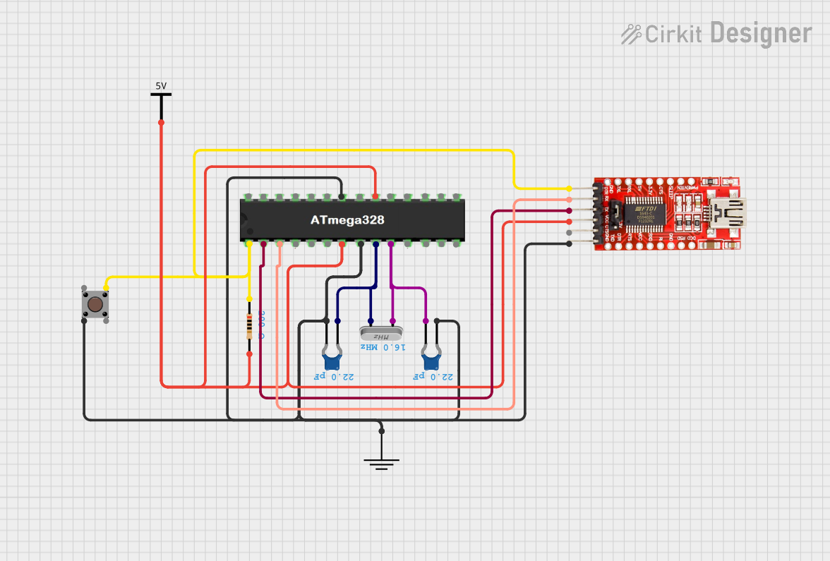
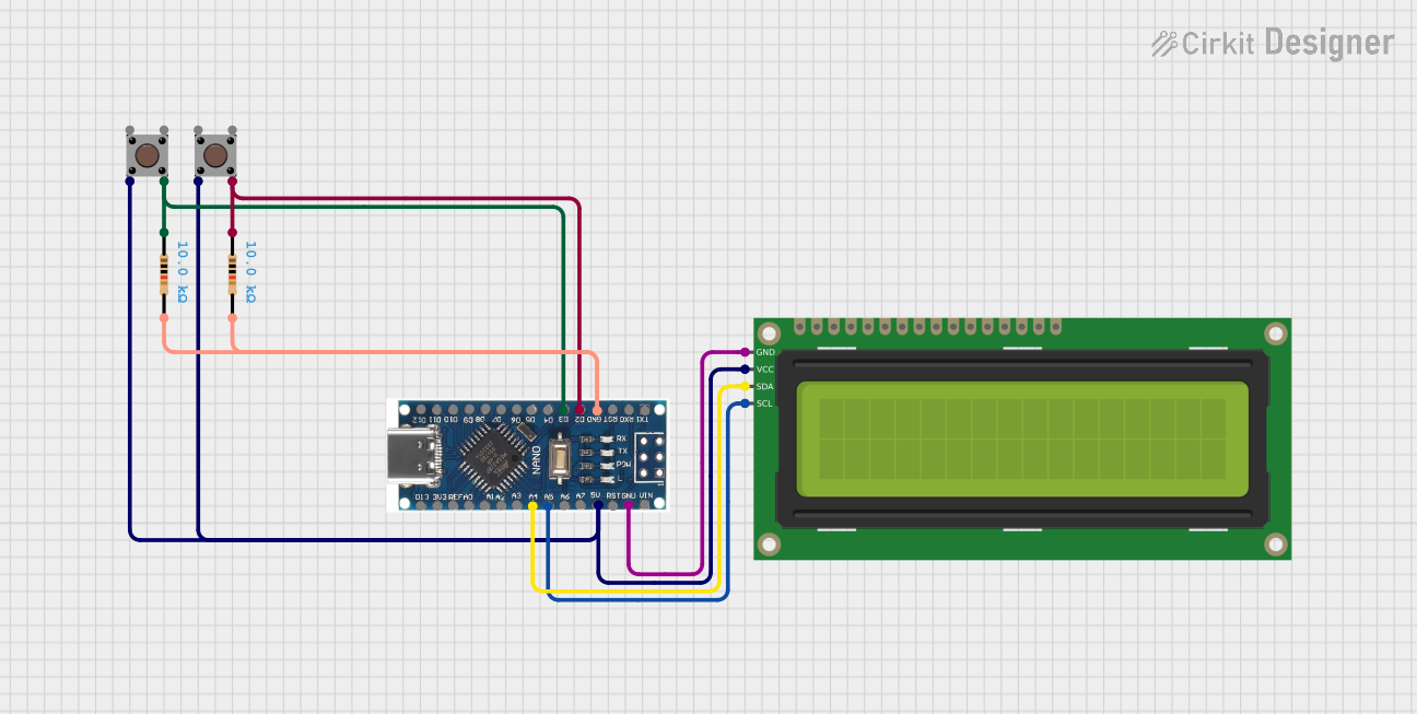
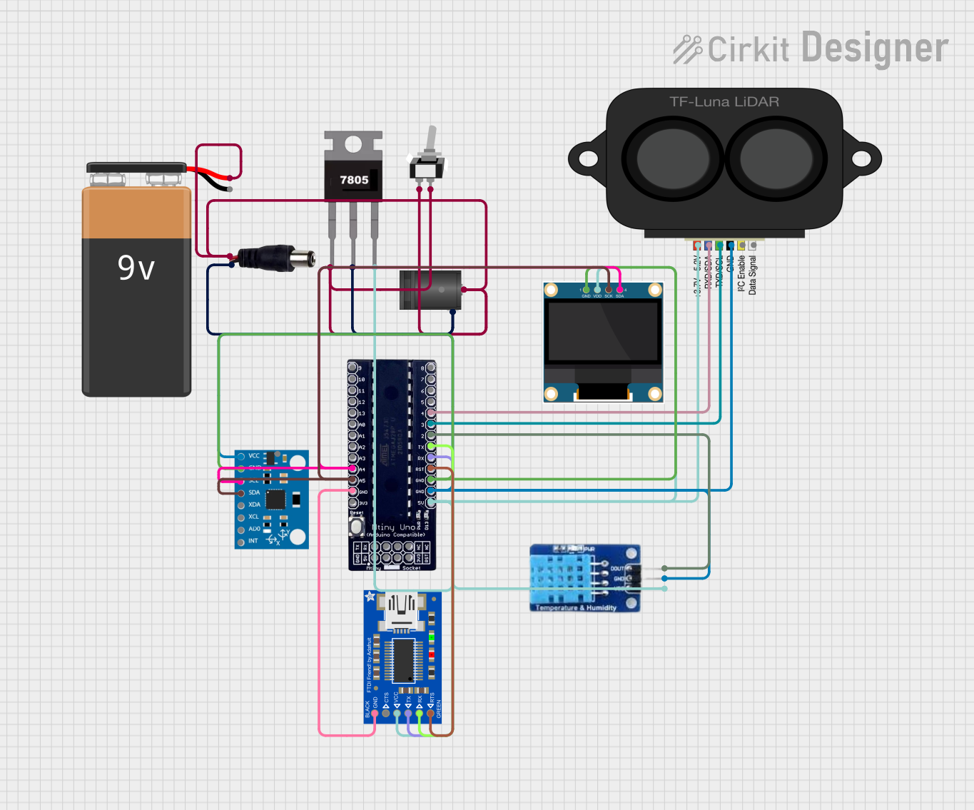
Explore Projects Built with ATMEGA328

 Open Project in Cirkit Designer
 Open Project in Cirkit Designer
 Open Project in Cirkit Designer
 Open Project in Cirkit Designer
Explore Projects Built with ATMEGA328

 Open Project in Cirkit Designer
 Open Project in Cirkit Designer
 Open Project in Cirkit Designer
 Open Project in Cirkit Designer
Common Applications
- DIY electronics projects
- Prototyping and educational tools
- Sensor networks
- Robotics
- Home automation systems
Technical Specifications
Key Technical Details
- Flash Memory: 32KB
- SRAM: 2KB
- EEPROM: 1KB
- I/O Pins: 23
- Clock Speed: Up to 20MHz
- Operating Voltage: 1.8 - 5.5V
- Analog-to-Digital Converter: 6-channel, 10-bit
Pin Configuration and Descriptions
| Pin Number | Name | Description |
|---|---|---|
| 1 | PC6 | Reset/Input/Output Pin |
| 2-3 | PD0-PD1 | Serial Communication (RX/TX) |
| 4-5 | PD2-PD3 | External Interrupts (INT0/INT1) |
| 6-11 | PD4-PD7, PB0-PB1 | General Purpose I/O Pins |
| 12-19 | PB2-PB5, PC0-PC3 | General Purpose I/O Pins, SPI Interface, Analog Inputs |
| 20-22 | PC4-PC5, AVCC | I2C Interface (SDA/SCL), Analog Power Supply |
| 23 | GND | Ground Pin |
| 24 | AREF | Analog Reference Pin |
| 25-28 | GND, VCC, GND, VCC | Power Supply Pins |
| 29-32 | PC6-PC7, PD0-PD1 | General Purpose I/O Pins, Clock Oscillator Pins |
Usage Instructions
Integrating ATMEGA328 into a Circuit
- Power Supply: Connect the VCC pins to a 5V power supply and the GND pins to ground. Ensure that the power supply is stable and within the operating voltage range.
- Clock Source: The ATMEGA328 can use an internal or external clock source. For precise timing applications, connect a crystal oscillator to the XTAL1 and XTAL2 pins.
- Programming: To program the ATMEGA328, you can use an ISP (In-System Programmer) or bootload through the serial interface using a USB-to-serial converter.
- I/O Configuration: Configure the I/O pins according to your application needs. Remember to set the data direction registers appropriately in your code.
Best Practices
- Use decoupling capacitors close to the power supply pins to filter out noise.
- Ensure that the I/O pins are not sourcing or sinking current beyond their capacity.
- Avoid exposing the microcontroller to temperatures outside the specified range in the datasheet.
- Use a pull-up resistor on the RESET pin to prevent unintended resets.
Troubleshooting and FAQs
Common Issues
- Microcontroller not responding: Ensure that the power supply is connected correctly and the clock source is functioning.
- Program not running: Verify that the ATMEGA328 has been programmed correctly and the fuse bits are set as intended.
- Unexpected behavior: Check for any shorts or open circuits in the board. Ensure that the I/O pins are not overloaded.
Solutions and Tips
- Always double-check connections before powering up the circuit.
- Use a multimeter to verify voltage levels and continuity.
- If using an external programmer, ensure that it is compatible with the ATMEGA328.
FAQs
Q: Can I use the Arduino IDE to program the ATMEGA328? A: Yes, the Arduino IDE supports the ATMEGA328, and you can use it to write and upload sketches.
Q: What is the maximum current that each I/O pin can handle? A: Each I/O pin can source or sink up to 40 mA, but the total I/O pin current must not exceed 200 mA.
Q: How do I reset the ATMEGA328? A: You can reset the ATMEGA328 by pulling the RESET pin low.
Q: Can the ATMEGA328 run on a 3.3V power supply? A: Yes, the ATMEGA328 can operate at 3.3V, but the maximum clock frequency will be lower than at 5V.
Example Code for Arduino UNO
// Blink LED connected to pin 13
void setup() {
  pinMode(13, OUTPUT); // Set pin 13 as an output
}

void loop() {
  digitalWrite(13, HIGH); // Turn the LED on
  delay(1000);           // Wait for a second
  digitalWrite(13, LOW);  // Turn the LED off
  delay(1000);           // Wait for a second
}
Note: The above code is a simple example to blink an LED on an Arduino UNO board, which uses the ATMEGA328 microcontroller. The comments are wrapped to comply with the 80 character line length limit.