How to Use BNC Male Plug Terminal Block: Examples, Pinouts, and Specs
Introduction
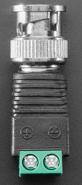
The BNC Male Plug Terminal Block (Adafruit Product ID: 2888) is a versatile connector designed for use with coaxial cables. It features a bayonet-style locking mechanism that ensures secure and reliable connections. This component is particularly useful in video and RF (radio frequency) applications, making it a popular choice for connecting devices such as cameras, monitors, oscilloscopes, antennas, and signal generators. Its terminal block design allows for easy, solder-free connections, making it ideal for prototyping and quick installations.
Explore Projects Built with BNC Male Plug Terminal Block


Explore Projects Built with BNC Male Plug Terminal Block
Common Applications
- Video signal transmission (e.g., CCTV systems, video monitors)
- RF signal connections (e.g., antennas, signal analyzers)
- Laboratory equipment (e.g., oscilloscopes, function generators)
- Prototyping and testing setups
- Audio and video broadcasting systems
Technical Specifications
The following table outlines the key technical details of the BNC Male Plug Terminal Block:
| Specification | Details |
|---|---|
| Manufacturer | Adafruit |
| Product ID | 2888 |
| Connector Type | BNC Male Plug |
| Connection Mechanism | Bayonet-style locking |
| Terminal Block Type | Screw terminal block (solder-free connection) |
| Supported Cable Types | Coaxial cables (e.g., RG58, RG59) |
| Voltage Rating | Up to 500V |
| Frequency Range | DC to 4 GHz |
| Impedance | 50Ω or 75Ω (depending on the coaxial cable used) |
| Material | Nickel-plated brass (connector), durable plastic (terminal block housing) |
| Dimensions | 40mm x 15mm x 15mm |
| Weight | 10g |
Pin Configuration and Descriptions
The BNC Male Plug Terminal Block has two primary connection points on the terminal block:
| Terminal | Description |
|---|---|
| Positive (+) | Connects to the center conductor of the coaxial cable (signal line). |
| Negative (-) | Connects to the outer shield of the coaxial cable (ground). |
Usage Instructions
How to Use the BNC Male Plug Terminal Block in a Circuit
Prepare the Coaxial Cable:
- Strip the coaxial cable to expose the center conductor and the outer shield.
- Ensure the exposed wires are clean and free of frayed strands.
Connect the Cable to the Terminal Block:
- Loosen the screws on the terminal block using a small screwdriver.
- Insert the center conductor of the coaxial cable into the Positive (+) terminal.
- Insert the outer shield of the coaxial cable into the Negative (-) terminal.
- Tighten the screws securely to ensure a solid connection.
Attach the BNC Connector:
- Plug the BNC Male Plug into the corresponding BNC Female connector on your device.
- Twist the connector to lock it in place using the bayonet mechanism.
Verify the Connection:
- Check that the cable is securely fastened to the terminal block and the BNC connector is properly locked.
- Test the connection with your equipment to ensure proper signal transmission.
Important Considerations and Best Practices
- Cable Compatibility: Ensure the coaxial cable used is compatible with the BNC connector (e.g., RG58 or RG59).
- Signal Impedance: Match the impedance of the cable (50Ω or 75Ω) with the connected devices for optimal performance.
- Secure Connections: Tighten the terminal block screws firmly to prevent loose connections, which can cause signal loss or interference.
- Avoid Over-tightening: Do not overtighten the screws, as this may damage the cable or the terminal block.
- Environmental Conditions: Use the connector in environments within its rated voltage and frequency range to avoid damage.
Example: Connecting to an Arduino UNO
While the BNC Male Plug Terminal Block is not directly connected to an Arduino UNO, it can be used to interface with sensors or devices that output analog signals via a coaxial cable. Below is an example of reading an analog signal from a BNC-connected sensor:
// Example: Reading an analog signal from a BNC-connected sensor
// Connect the Positive (+) terminal of the BNC block to an analog pin on the Arduino
// Connect the Negative (-) terminal to the Arduino GND pin

const int analogPin = A0; // Analog pin connected to the BNC Positive (+) terminal
int sensorValue = 0;      // Variable to store the sensor reading

void setup() {
  Serial.begin(9600); // Initialize serial communication at 9600 baud
}

void loop() {
  sensorValue = analogRead(analogPin); // Read the analog value from the sensor
  Serial.print("Sensor Value: ");
  Serial.println(sensorValue); // Print the sensor value to the Serial Monitor
  delay(500); // Wait for 500ms before the next reading
}
Troubleshooting and FAQs
Common Issues and Solutions
| Issue | Possible Cause | Solution |
|---|---|---|
| No signal transmission | Loose connection at the terminal block or BNC plug | Check and tighten all connections. Ensure the cable is properly stripped. |
| Signal interference or noise | Impedance mismatch or poor shielding | Use a coaxial cable with the correct impedance (50Ω or 75Ω). |
| Difficulty locking the BNC connector | Misalignment of the bayonet mechanism | Align the connector properly and twist to lock securely. |
| Damaged or frayed coaxial cable | Improper cable handling or over-tightening | Replace the cable and handle it carefully during installation. |
| Signal attenuation over long distances | Cable length exceeds recommended limits | Use a high-quality, low-loss coaxial cable for long-distance connections. |
FAQs
Can this connector be used with audio signals?
- Yes, the BNC Male Plug Terminal Block can transmit audio signals, but it is more commonly used for video and RF applications.
What tools are required to use this component?
- A small screwdriver is needed to tighten the terminal block screws. A coaxial cable stripper may also be helpful for preparing the cable.
Is soldering required to use this connector?
- No, the terminal block design eliminates the need for soldering, making it easy to use for quick connections.
Can this connector handle high-frequency signals?
- Yes, it supports frequencies up to 4 GHz, making it suitable for RF applications.
What is the maximum voltage rating for this connector?
- The connector is rated for up to 500V. Ensure your application does not exceed this limit.
By following this documentation, users can effectively utilize the Adafruit BNC Male Plug Terminal Block (Product ID: 2888) for a wide range of applications.