Cirkit Designer Logo
Cirkit Designer
Your all-in-one circuit design IDE
Home / 
Component Documentation

How to Use usb module: Examples, Pinouts, and Specs

Image of usb module
Cirkit Designer LogoDesign with usb module in Cirkit Designer

Introduction

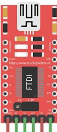
The USB Converter Module is an essential component designed to facilitate communication between a computer and various USB devices. This module is commonly used in applications where USB connectivity is required for peripherals such as keyboards, mice, printers, and external storage devices. It is also used in embedded systems to provide USB functionality to microcontrollers and other electronics.

Explore Projects Built with usb module

Use Cirkit Designer to design, explore, and prototype these projects online. Some projects support real-time simulation. Click "Open Project" to start designing instantly!
Arduino UNO and SIM800L GSM Module for Wireless Communication with LM2596 Power Regulation
Image of theft: A project utilizing usb module in a practical application
This circuit features an Arduino UNO microcontroller interfaced with a SIM 800L GSM module for communication purposes. The SIM 800L is powered by an LM2596 step-down module, which provides the necessary voltage regulation. The Arduino communicates with the SIM 800L via digital pins D2 and D3 for RX and TX respectively.
Cirkit Designer LogoOpen Project in Cirkit Designer
Arduino GSM Security System with Motion Detection and Light Sensing
Image of Smart Home Security: A project utilizing usb module in a practical application
This circuit is designed to interface an Arduino UNO with a SIM800L GSM module, PIR sensor, photocell, buzzer, and multiple LEDs. It is likely intended for environmental monitoring and alerting, with the capability to communicate over GSM for remote notifications. The LM2596 module provides voltage regulation for the GSM module.
Cirkit Designer LogoOpen Project in Cirkit Designer
Arduino Mega 2560 Based Security System with Fingerprint Authentication and SMS Alerts
Image of Door security system: A project utilizing usb module in a practical application
This circuit features an Arduino Mega 2560 microcontroller interfaced with a SIM800L GSM module, two fingerprint scanners, an I2C LCD display, an IR sensor, and a piezo buzzer. Power management is handled by a PowerBoost 1000 Basic Pad USB, a TP4056 charging module, and a Li-ion 18650 battery, with an option to use a Mini AC-DC 110V-230V to 5V 700mA module for direct power supply. The primary functionality appears to be a security system with GSM communication capabilities, biometric access control, and visual/audible feedback.
Cirkit Designer LogoOpen Project in Cirkit Designer
Dual Hub Motor Control System with USB to TTL Interface and Relay Switching
Image of Hub Motor & servo motor Connection: A project utilizing usb module in a practical application
This circuit is designed to control two hub motors using a HUB driver, powered by a DC-DC converter and a power module. The USB to TTL converter allows for communication with the HUB driver, and a 5V relay module is used to switch the motors on and off.
Cirkit Designer LogoOpen Project in Cirkit Designer

Explore Projects Built with usb module

Use Cirkit Designer to design, explore, and prototype these projects online. Some projects support real-time simulation. Click "Open Project" to start designing instantly!
Image of theft: A project utilizing usb module in a practical application
Arduino UNO and SIM800L GSM Module for Wireless Communication with LM2596 Power Regulation
This circuit features an Arduino UNO microcontroller interfaced with a SIM 800L GSM module for communication purposes. The SIM 800L is powered by an LM2596 step-down module, which provides the necessary voltage regulation. The Arduino communicates with the SIM 800L via digital pins D2 and D3 for RX and TX respectively.
Cirkit Designer LogoOpen Project in Cirkit Designer
Image of Smart Home Security: A project utilizing usb module in a practical application
Arduino GSM Security System with Motion Detection and Light Sensing
This circuit is designed to interface an Arduino UNO with a SIM800L GSM module, PIR sensor, photocell, buzzer, and multiple LEDs. It is likely intended for environmental monitoring and alerting, with the capability to communicate over GSM for remote notifications. The LM2596 module provides voltage regulation for the GSM module.
Cirkit Designer LogoOpen Project in Cirkit Designer
Image of Door security system: A project utilizing usb module in a practical application
Arduino Mega 2560 Based Security System with Fingerprint Authentication and SMS Alerts
This circuit features an Arduino Mega 2560 microcontroller interfaced with a SIM800L GSM module, two fingerprint scanners, an I2C LCD display, an IR sensor, and a piezo buzzer. Power management is handled by a PowerBoost 1000 Basic Pad USB, a TP4056 charging module, and a Li-ion 18650 battery, with an option to use a Mini AC-DC 110V-230V to 5V 700mA module for direct power supply. The primary functionality appears to be a security system with GSM communication capabilities, biometric access control, and visual/audible feedback.
Cirkit Designer LogoOpen Project in Cirkit Designer
Image of Hub Motor & servo motor Connection: A project utilizing usb module in a practical application
Dual Hub Motor Control System with USB to TTL Interface and Relay Switching
This circuit is designed to control two hub motors using a HUB driver, powered by a DC-DC converter and a power module. The USB to TTL converter allows for communication with the HUB driver, and a 5V relay module is used to switch the motors on and off.
Cirkit Designer LogoOpen Project in Cirkit Designer

Common Applications and Use Cases

  • USB to Serial conversion for microcontroller projects
  • USB interface for custom keyboards or other HID devices
  • Data transfer interface for external storage devices
  • Debugging and programming interface for embedded systems

Technical Specifications

Key Technical Details

  • Operating Voltage: Typically 3.3V or 5V, depending on the module
  • Output Current: Varies by module design
  • Data Transfer Rate: Up to 480 Mbps for USB 2.0 modules
  • Compatibility: USB 2.0, backward compatible with USB 1.1

Pin Configuration and Descriptions

Pin Number Pin Name Description
1 VCC Power supply (3.3V or 5V)
2 D- USB Data minus
3 D+ USB Data plus
4 ID USB ID, typically not connected
5 GND Ground

Usage Instructions

How to Use the Component in a Circuit

  1. Power Supply: Connect the VCC pin to a suitable power source (3.3V or 5V as per the module's requirement).
  2. Ground Connection: Connect the GND pin to the ground of the power supply.
  3. Data Lines: Connect the D+ and D- pins to the corresponding data lines of the USB device or host.
  4. Mounting: Secure the module onto the PCB or breadboard, ensuring proper ESD precautions.

Important Considerations and Best Practices

  • Ensure that the power supply voltage matches the module's requirements.
  • Use a decoupling capacitor close to the VCC pin to filter out voltage spikes.
  • Keep the USB data lines as short as possible to minimize signal degradation.
  • Avoid running USB data lines near high-frequency signals to prevent interference.
  • Use proper ESD protection when handling the module to prevent damage.

Troubleshooting and FAQs

Common Issues Users Might Face

  • Device Not Recognized: Check the connections and ensure that the drivers are installed correctly.
  • Data Transfer Errors: Verify the integrity of the data lines and the quality of the solder joints.
  • Power Issues: Ensure that the module is receiving the correct voltage and that the power supply can handle the current requirements.

Solutions and Tips for Troubleshooting

  • Double-check the wiring against the pin configuration table.
  • Use a multimeter to verify the voltage levels at the VCC and GND pins.
  • If using with an Arduino UNO, ensure that the board is set to the correct COM port.
  • Check for any visible damage to the module or solder joints.

FAQs

Q: Can I use this module to program an Arduino? A: Yes, some USB converter modules can be used to program Arduino boards that have a serial bootloader.

Q: Is this module compatible with USB 3.0 devices? A: While the module can connect to USB 3.0 devices, it will only operate at USB 2.0 speeds.

Q: How can I extend the USB cable length without losing signal quality? A: Use a USB repeater or an active USB extension cable for longer distances.

Example Code for Arduino UNO

// Example code to communicate with the USB Converter Module
// This code is for demonstration purposes and may require additional setup.

void setup() {
  // Start the serial communication at 9600 baud rate
  Serial.begin(9600);
}

void loop() {
  // Check if data is available to read from the USB converter
  if (Serial.available() > 0) {
    // Read the incoming byte:
    char incomingByte = Serial.read();

    // Echo the incoming byte back to the USB converter
    Serial.write(incomingByte);
  }
}

Note: The above code is a simple echo program that sends back any data received from the USB converter. This can be used to test the communication between an Arduino UNO and the USB converter module. Ensure that the correct drivers for the USB converter are installed on the computer.