How to Use BN- 220 GPS: Examples, Pinouts, and Specs
Introduction
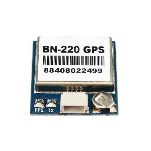
The BN-220 GPS module by Beitian is a compact, high-performance GPS receiver with an integrated ceramic antenna, designed for a wide range of applications that require precise location tracking. It supports multiple satellite systems, including GPS, GLONASS, and BeiDou, ensuring high accuracy and reliability. Common applications include drones, unmanned aerial vehicles (UAVs), robotics, vehicle tracking, and other navigation systems.
Explore Projects Built with BN- 220 GPS
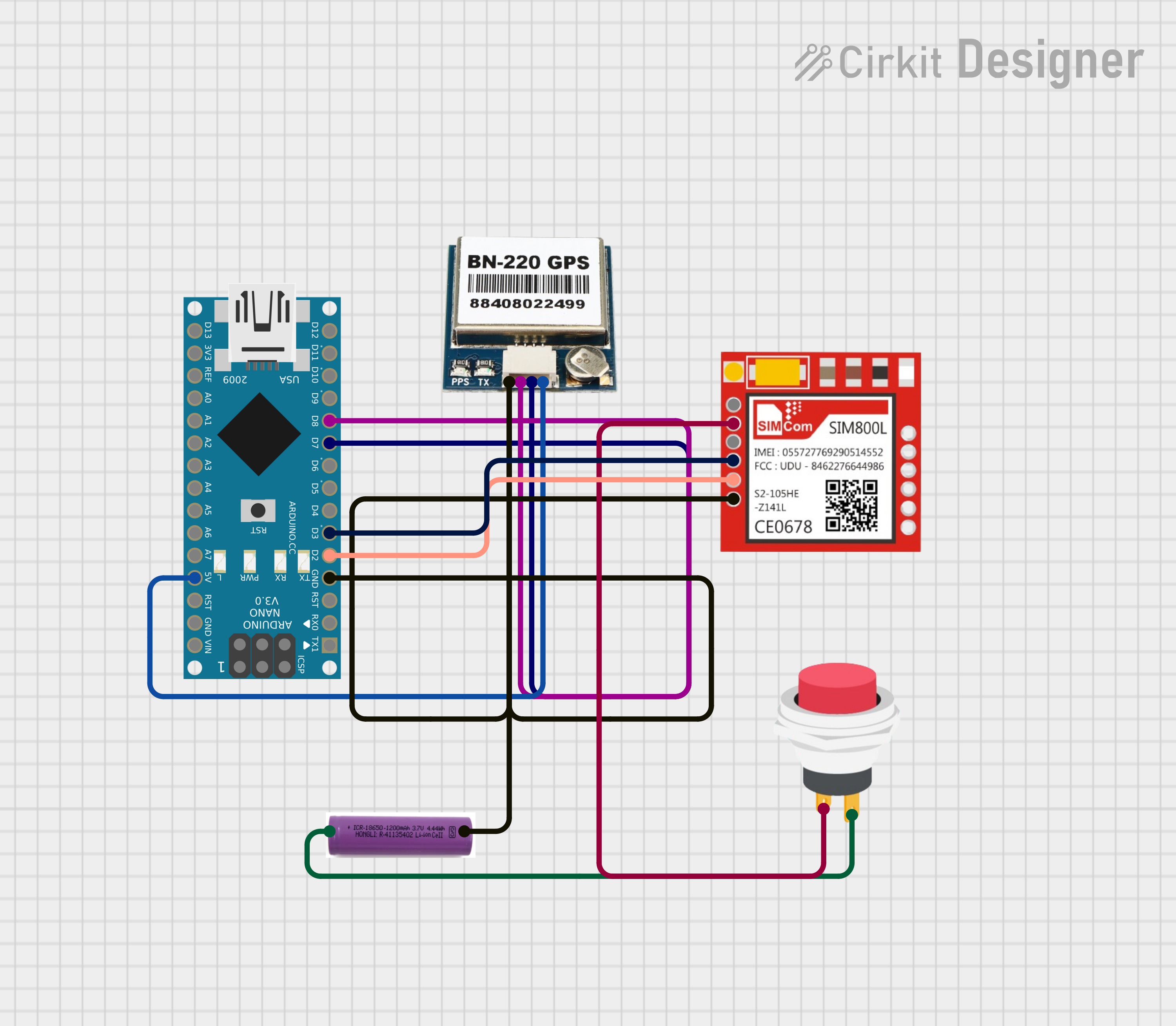
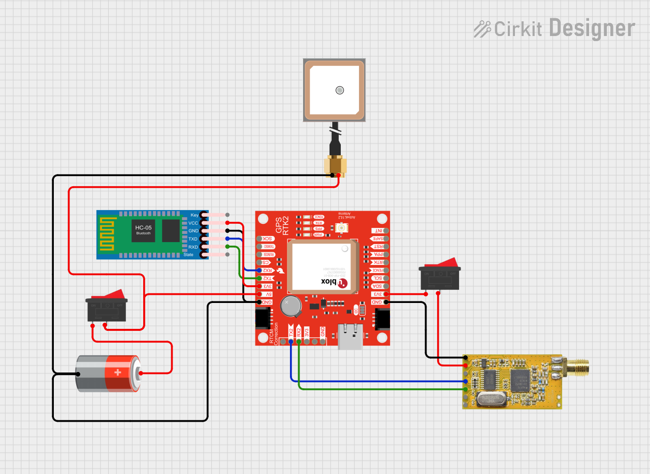

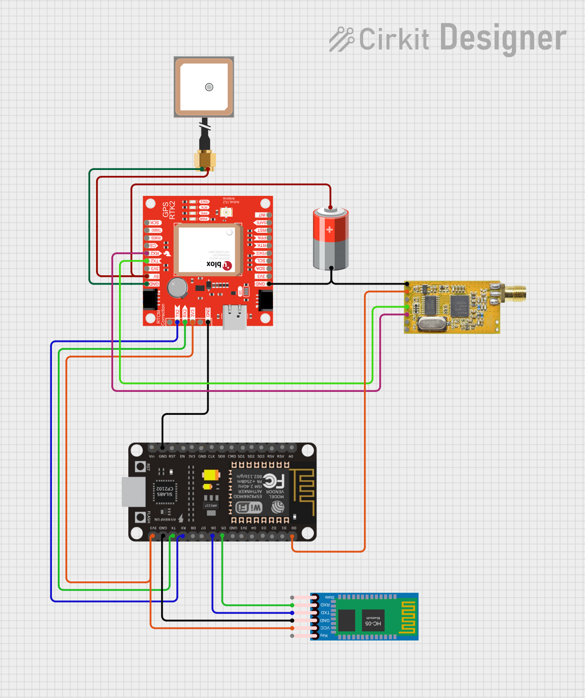
Explore Projects Built with BN- 220 GPS
Technical Specifications
General Features
- Receiver Type: 72-channel u-blox M8 engine
- GPS/QZSS L1 C/A, GLONASS L10F, BeiDou B1
- SBAS: WAAS, EGNOS, MSAS
- Galileo-ready E1B/C (firmware update required)
- Nav. Update Rate: Single GNSS: up to 18 Hz, 2 Concurrent GNSS: up to 10 Hz
- Position Accuracy: 2.0 m CEP
- Acquisition Times: Cold starts: 26s, Aided starts: 2s, Reacquisition: 1s
- Sensitivity: Tracking & Nav: –167 dBm, Cold starts: –148 dBm, Hot starts: –156 dBm
- Operating Temperature: -40°C to 85°C
Electrical Characteristics
- Supply Voltage: 3.0V - 5.5V
- Power Consumption: 23mA at 3.0V (typical)
Pin Configuration
| Pin Number | Description | Voltage Level |
|---|---|---|
| 1 | VCC | 3.0V - 5.5V |
| 2 | TX (Transmit) | 3.3V |
| 3 | RX (Receive) | 3.3V |
| 4 | GND (Ground) | 0V |
Usage Instructions
Integration into a Circuit
- Power Supply: Connect the VCC pin to a 3.0V - 5.5V power source. Ensure that the power supply is stable and within the specified voltage range to avoid damaging the module.
- Data Communication: Connect the TX and RX pins to the corresponding RX and TX pins of your microcontroller or UART interface. Note that the TX pin of the BN-220 should go to the RX pin of the microcontroller and vice versa.
- Grounding: Connect the GND pin to the ground of your system to complete the circuit.
Best Practices
- Place the module with a clear view of the sky to ensure optimal satellite signal reception.
- Avoid placing the module near high-frequency emitting devices to minimize interference.
- Use a proper antenna if additional range or signal quality is required.
- Ensure that the UART interface is configured to the correct baud rate, typically 9600 bps for the BN-220.
Example Code for Arduino UNO
#include <SoftwareSerial.h>

// Define the RX and TX pins connected to the BN-220 module
#define GPS_RX_PIN 3 // Connect to TX of GPS
#define GPS_TX_PIN 4 // Connect to RX of GPS

// Set up the serial connection to the GPS module
SoftwareSerial gpsSerial(GPS_RX_PIN, GPS_TX_PIN);

void setup() {
  // Start the Arduino hardware serial and the software serial for GPS
  Serial.begin(9600);
  gpsSerial.begin(9600);

  Serial.println("BN-220 GPS Module Test");
}

void loop() {
  // Check if data is available from the GPS module
  if (gpsSerial.available()) {
    // Read the data from the GPS module and output it to the hardware serial
    Serial.write(gpsSerial.read());
  }
}
Troubleshooting and FAQs
Common Issues
- No Data Output: Ensure that the wiring is correct and the module is powered. Check the baud rate settings on both the GPS module and the microcontroller.
- Inaccurate Position: Make sure the module has a clear view of the sky. In urban areas or indoors, the signal may be obstructed, leading to less accurate readings.
- Intermittent Signal: Check for sources of electromagnetic interference nearby. Relocate the module or shield it appropriately.
FAQs
Q: How long does it take for the BN-220 to get a fix? A: The time to first fix (TTFF) can vary. Cold starts may take up to 26 seconds, while aided starts can be as quick as 2 seconds.
Q: Can the BN-220 be used for indoor navigation? A: The BN-220 is optimized for outdoor use. Indoor navigation may be possible but with reduced accuracy and reliability.
Q: What is the default baud rate of the BN-220? A: The default baud rate is typically set to 9600 bps.
Q: Does the BN-220 have a built-in battery for memory backup? A: The BN-220 does not typically come with a built-in battery. External memory backup solutions may be required for rapid start-up.
For further assistance, please refer to the manufacturer's support resources or contact technical support.