How to Use TSW010: Examples, Pinouts, and Specs
Introduction
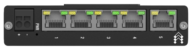
The TSW010, manufactured by Teltonika, is a high-performance, low-power electronic switch designed for signal routing and control. Its compact design and versatility make it suitable for handling both analog and digital signals. The TSW010 is widely used in applications requiring efficient signal management, such as communication systems, industrial automation, and consumer electronics.
Explore Projects Built with TSW010
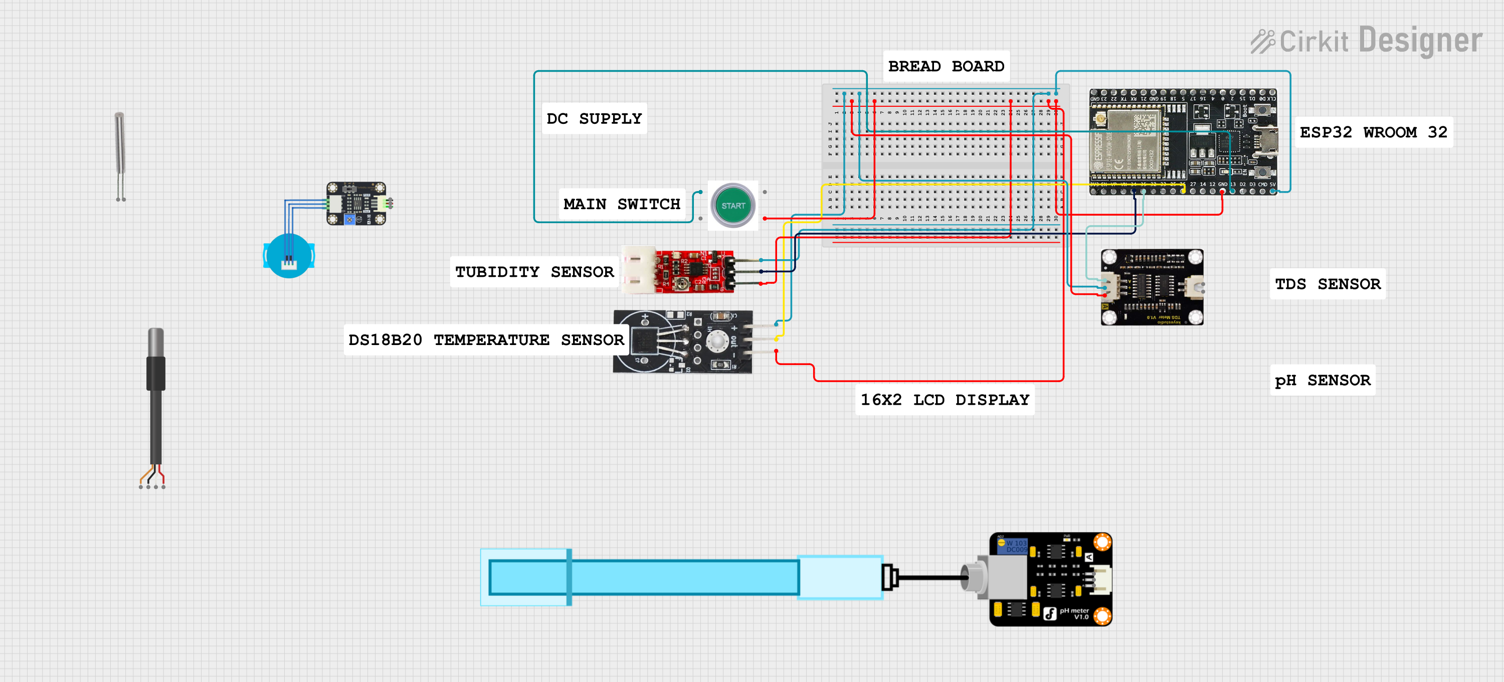


Explore Projects Built with TSW010
Common Applications and Use Cases
- Signal routing in communication systems
- Analog and digital signal switching in industrial automation
- Low-power control circuits in consumer electronics
- Multiplexing and demultiplexing in embedded systems
- General-purpose switching in prototyping and development projects
Technical Specifications
The TSW010 is designed to deliver reliable performance while maintaining low power consumption. Below are its key technical specifications:
| Parameter | Value |
|---|---|
| Operating Voltage | 1.8V to 5.5V |
| Maximum Current | 50mA |
| On-Resistance (RON) | 1.5Ω (typical) |
| Switching Speed | 10ns (typical) |
| Signal Range | 0V to VCC |
| Power Consumption | <1µA (standby mode) |
| Operating Temperature | -40°C to +85°C |
| Package Type | SOT-23-6 |
Pin Configuration and Descriptions
The TSW010 features a 6-pin SOT-23 package. The pinout and descriptions are as follows:
| Pin Number | Pin Name | Description |
|---|---|---|
| 1 | VCC | Power supply input (1.8V to 5.5V) |
| 2 | GND | Ground |
| 3 | IN | Control input for switching (logic high/low) |
| 4 | OUT1 | Output 1 (connected to COM when IN is high) |
| 5 | OUT2 | Output 2 (connected to COM when IN is low) |
| 6 | COM | Common terminal for signal routing |
Usage Instructions
The TSW010 is straightforward to use in a circuit. Below are the steps and considerations for integrating it into your design:
How to Use the TSW010 in a Circuit
- Power Supply: Connect the VCC pin to a stable power source within the range of 1.8V to 5.5V. Connect the GND pin to the circuit ground.
- Control Signal: Apply a logic signal (high or low) to the IN pin to control the switching behavior:
- Logic HIGH: COM connects to OUT1.
- Logic LOW: COM connects to OUT2.
- Signal Routing: Connect the signal source to the COM pin and the desired output paths to OUT1 and OUT2.
- Load Considerations: Ensure the load connected to the outputs does not exceed the maximum current rating of 50mA.
Important Considerations and Best Practices
- Voltage Levels: Ensure the control signal applied to the IN pin matches the operating voltage range of the TSW010.
- Signal Integrity: For high-frequency signals, minimize trace lengths to reduce signal degradation.
- Thermal Management: Operate the TSW010 within its specified temperature range (-40°C to +85°C) to avoid performance issues.
- Decoupling Capacitor: Place a 0.1µF ceramic capacitor close to the VCC pin to stabilize the power supply.
Example: Using TSW010 with Arduino UNO
The TSW010 can be easily controlled using an Arduino UNO. Below is an example circuit and code to toggle the switch:
Circuit Connections
- Connect the VCC pin of the TSW010 to the 5V pin of the Arduino.
- Connect the GND pin of the TSW010 to the GND pin of the Arduino.
- Connect the IN pin of the TSW010 to digital pin 7 of the Arduino.
- Connect the COM pin to the signal source.
- Connect OUT1 and OUT2 to the desired output paths.
Arduino Code
// TSW010 Control Example
// This code toggles the TSW010 switch every second using Arduino UNO.

#define SWITCH_PIN 7  // Define the pin connected to the IN pin of TSW010

void setup() {
  pinMode(SWITCH_PIN, OUTPUT);  // Set the pin as an output
}

void loop() {
  digitalWrite(SWITCH_PIN, HIGH);  // Set IN pin HIGH (COM connects to OUT1)
  delay(1000);                     // Wait for 1 second
  digitalWrite(SWITCH_PIN, LOW);   // Set IN pin LOW (COM connects to OUT2)
  delay(1000);                     // Wait for 1 second
}
Troubleshooting and FAQs
Common Issues and Solutions
Switch Not Responding to Control Signal
- Cause: Incorrect voltage levels on the IN pin.
- Solution: Verify that the control signal matches the operating voltage range (1.8V to 5.5V).
Signal Degradation or Noise
- Cause: Long trace lengths or poor PCB layout.
- Solution: Minimize trace lengths and use proper grounding techniques.
Excessive Heat Generation
- Cause: Exceeding the maximum current rating or operating outside the temperature range.
- Solution: Ensure the load current is below 50mA and the ambient temperature is within -40°C to +85°C.
Unstable Operation
- Cause: Power supply noise or lack of decoupling.
- Solution: Add a 0.1µF decoupling capacitor near the VCC pin.
FAQs
Q1: Can the TSW010 handle bidirectional signals?
A1: Yes, the TSW010 can handle bidirectional signals as long as the voltage range is within 0V to VCC.
Q2: Is the TSW010 suitable for high-frequency signals?
A2: Yes, the TSW010 supports high-frequency signals, but proper PCB layout is essential to maintain signal integrity.
Q3: Can I use the TSW010 with a 3.3V microcontroller?
A3: Yes, the TSW010 is compatible with 3.3V systems as its operating voltage range is 1.8V to 5.5V.
Q4: What happens if the IN pin is left floating?
A4: Leaving the IN pin floating may result in unpredictable behavior. Always connect it to a defined logic level.