How to Use SW420: Examples, Pinouts, and Specs
Introduction
The SW420 is a tilt switch sensor module designed to detect changes in orientation or position. It activates when tilted beyond a certain angle, making it ideal for applications requiring motion or tilt detection. This component is widely used in alarm systems, robotics, and devices that need to monitor angular movement or orientation.
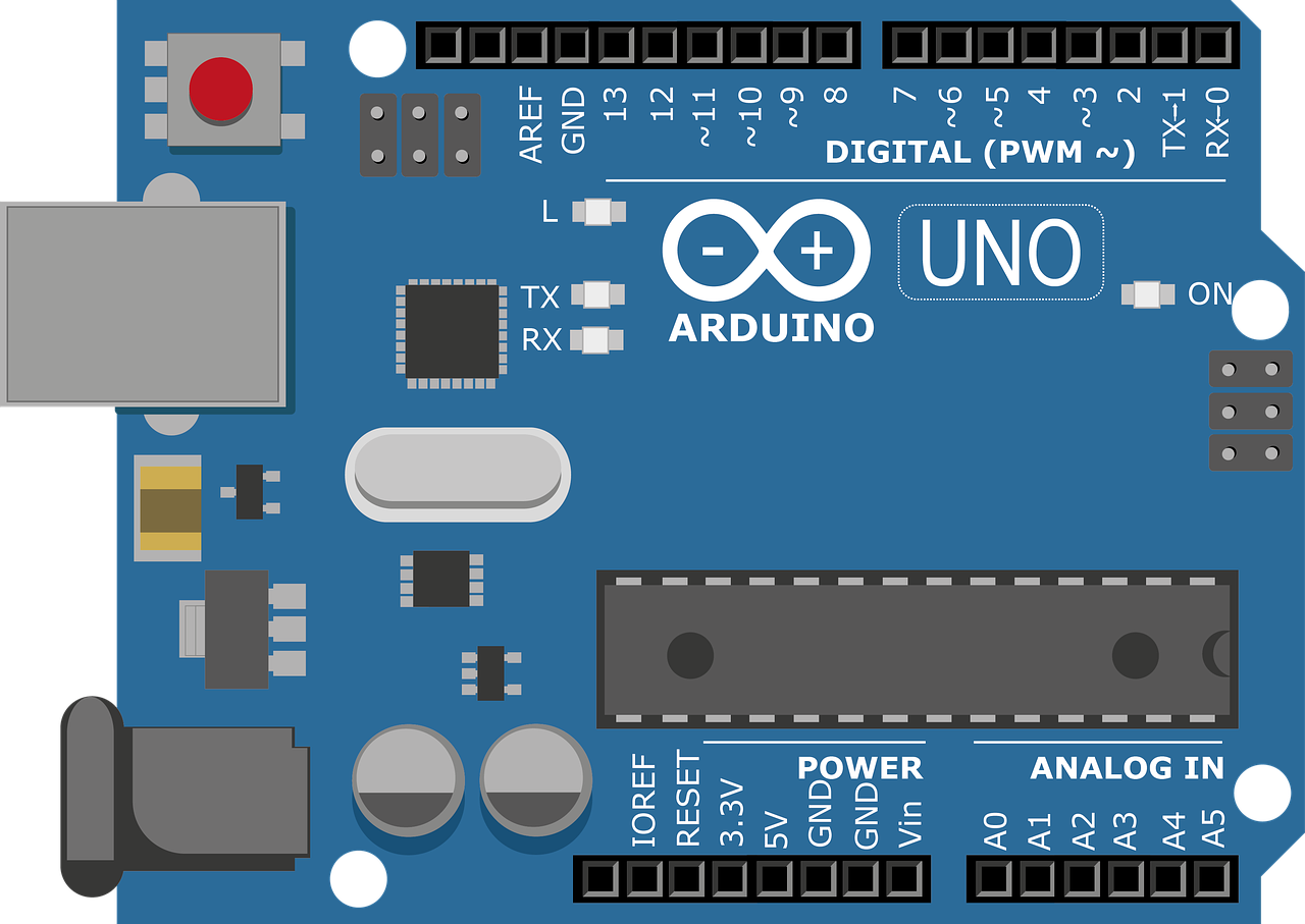
Manufactured by ARDUINO, the SW420 (Part ID: UNO) is a reliable and cost-effective solution for detecting tilt or vibration in electronic systems.
Explore Projects Built with SW420
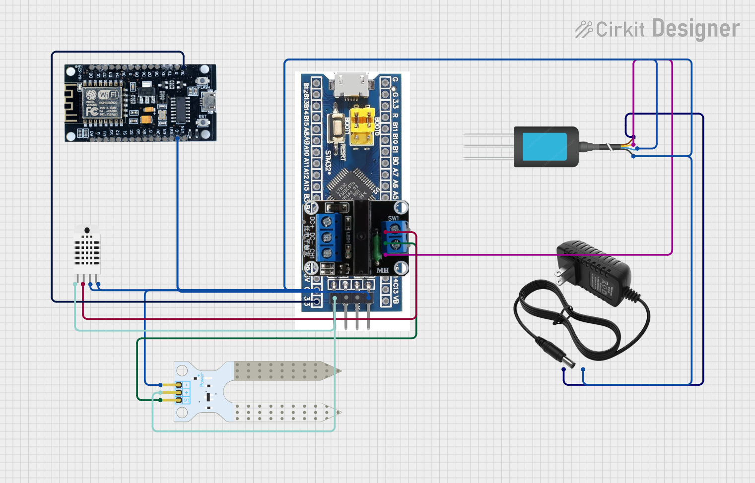


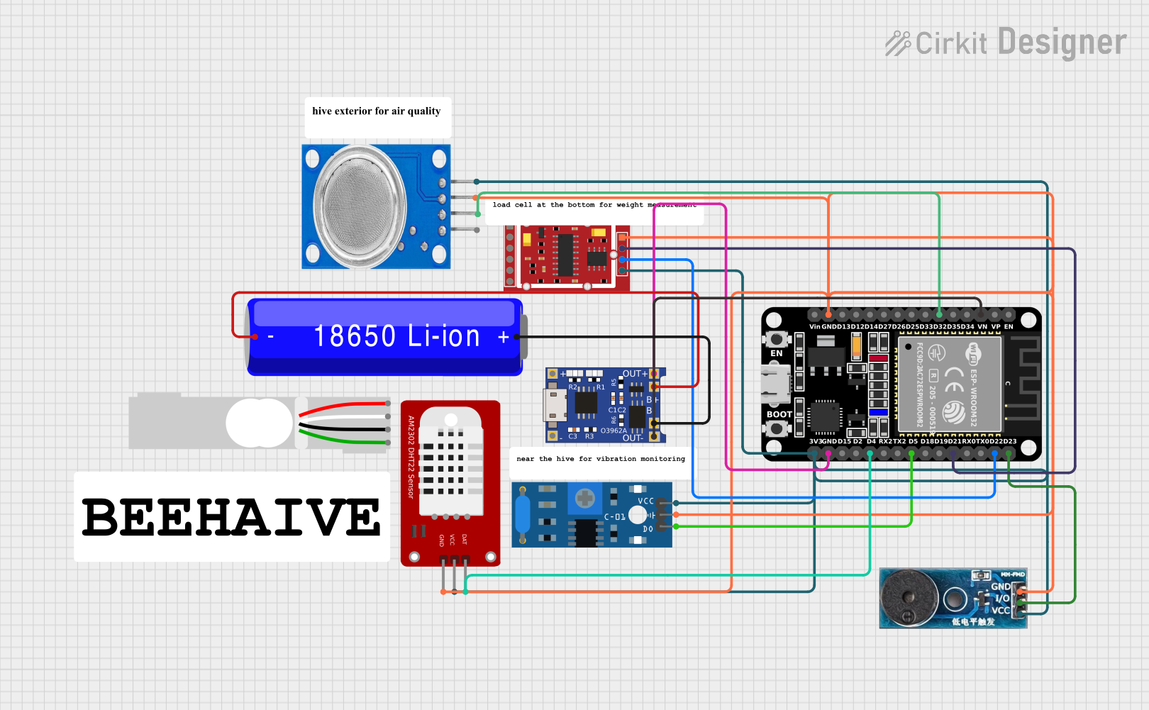
Explore Projects Built with SW420
Common Applications
- Anti-theft alarm systems
- Robotics and automation
- Motion detection in toys and gadgets
- Orientation monitoring in industrial equipment
- Earthquake detection systems
Technical Specifications
Key Technical Details
| Parameter | Value |
|---|---|
| Operating Voltage | 3.3V to 5V |
| Output Type | Digital (High/Low) |
| Sensitivity Adjustment | Via onboard potentiometer |
| Dimensions | 32mm x 14mm x 8mm |
| Operating Temperature | -40°C to +85°C |
| Detection Angle | Typically ±15° |
Pin Configuration and Descriptions
| Pin Name | Pin Number | Description |
|---|---|---|
| VCC | 1 | Power supply pin (3.3V to 5V) |
| GND | 2 | Ground pin |
| DO | 3 | Digital output pin (High when tilted, Low otherwise) |
Usage Instructions
How to Use the SW420 in a Circuit
- Power the Module: Connect the
VCCpin to a 3.3V or 5V power source and theGNDpin to the ground of your circuit. - Connect the Output: Attach the
DOpin to a digital input pin of your microcontroller (e.g., Arduino UNO). - Adjust Sensitivity: Use the onboard potentiometer to fine-tune the sensitivity of the tilt detection.
- Monitor Output: The
DOpin outputs a HIGH signal when the module is tilted and a LOW signal when it is stable.
Important Considerations and Best Practices
- Ensure the module is mounted securely to avoid false triggers due to vibrations.
- Avoid exposing the module to extreme temperatures or moisture, as this may affect its performance.
- Use pull-up or pull-down resistors if necessary to stabilize the digital output signal.
- When connecting to an Arduino UNO, ensure the power supply voltage matches the module's requirements.
Example Code for Arduino UNO
Below is an example code snippet to interface the SW420 with an Arduino UNO:
// SW420 Tilt Switch Example Code
// This code reads the digital output of the SW420 and prints the status to the Serial Monitor.

const int tiltPin = 2; // Connect the DO pin of SW420 to digital pin 2
int tiltState = 0;     // Variable to store the tilt state

void setup() {
  pinMode(tiltPin, INPUT); // Set the tilt pin as input
  Serial.begin(9600);      // Initialize serial communication at 9600 baud
}

void loop() {
  tiltState = digitalRead(tiltPin); // Read the state of the tilt switch

  if (tiltState == HIGH) {
    // If the tilt switch is activated
    Serial.println("Tilt detected!");
  } else {
    // If the tilt switch is stable
    Serial.println("No tilt detected.");
  }

  delay(500); // Wait for 500ms before reading again
}
Notes:
- Connect the
DOpin of the SW420 to pin 2 of the Arduino UNO. - Open the Serial Monitor (set to 9600 baud) to view the tilt detection status.
Troubleshooting and FAQs
Common Issues and Solutions
| Issue | Possible Cause | Solution |
|---|---|---|
| No output from the module | Incorrect wiring or loose connections | Verify all connections and ensure proper wiring. |
| False triggers or unstable output | Sensitivity set too high | Adjust the potentiometer to reduce sensitivity. |
| Module not responding | Power supply issue | Ensure the module is powered with 3.3V to 5V. |
| Output always HIGH or LOW | Faulty module or improper grounding | Check the module and ensure proper grounding. |
FAQs
Can the SW420 detect vibration as well as tilt?
- Yes, the SW420 can detect both tilt and vibration, depending on its orientation and sensitivity settings.
What is the maximum tilt angle it can detect?
- The SW420 typically detects tilt angles of ±15° from its stable position.
Can I use the SW420 with a 3.3V microcontroller?
- Yes, the SW420 operates within a voltage range of 3.3V to 5V, making it compatible with 3.3V systems.
How do I adjust the sensitivity?
- Use the onboard potentiometer to increase or decrease the sensitivity. Turn it clockwise to increase sensitivity and counterclockwise to decrease it.
By following this documentation, you can effectively integrate the SW420 tilt switch into your projects and troubleshoot any issues that arise.