Cirkit Designer Logo
Cirkit Designer
Your all-in-one circuit design IDE
Home / 
Component Documentation

How to Use 3104 push button: Examples, Pinouts, and Specs

Image of 3104 push button
Cirkit Designer LogoDesign with 3104 push button in Cirkit Designer

Introduction

The 3104 push button is a momentary switch that is widely used in electronic circuits. When the button is pressed, it closes the circuit, allowing electric current to flow through. Upon release, the button returns to its default position, opening the circuit and stopping the current. This simple yet versatile component is commonly found in applications such as input devices, control panels, and hobbyist projects, including interfacing with microcontrollers like the Arduino UNO.

Explore Projects Built with 3104 push button

Use Cirkit Designer to design, explore, and prototype these projects online. Some projects support real-time simulation. Click "Open Project" to start designing instantly!
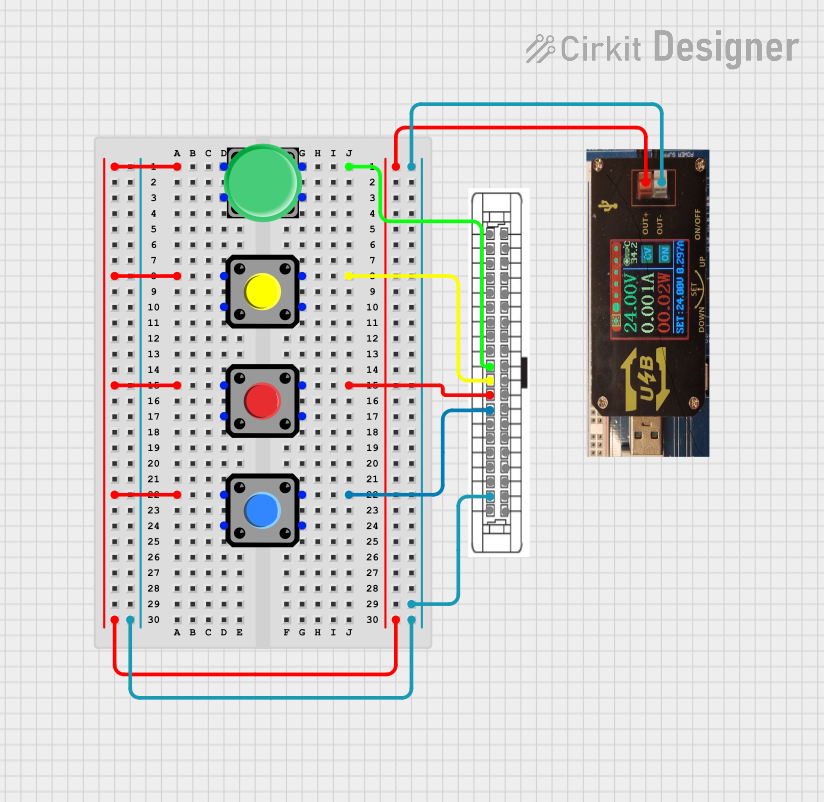
Pushbutton-Controlled Interface with 40-Pin Connector and UBS Power Supply
Image of connect 4: A project utilizing 3104 push button in a practical application
This circuit consists of a 40-pin connector interfacing with four pushbuttons and a UBS power supply. The pushbuttons are used as inputs to the connector, which then relays the signals to other components or systems. The UBS power supply provides the necessary 24V power to the pushbuttons and the common ground for the circuit.
Cirkit Designer LogoOpen Project in Cirkit Designer
24V Pushbutton Control Interface with 40-Pin Connector
Image of 4 på rad: A project utilizing 3104 push button in a practical application
This circuit consists of a 24V power supply unit (PSU) connected to four pushbuttons. Each pushbutton is wired such that pressing it will send a 24V signal to a corresponding general-purpose input (GP In) on a 40-pin connector. The common return path for the pushbuttons is connected to the 0V of the PSU, which is also connected to the common (Com) for input pins on the 40-pin connector, completing the circuit for each button press.
Cirkit Designer LogoOpen Project in Cirkit Designer
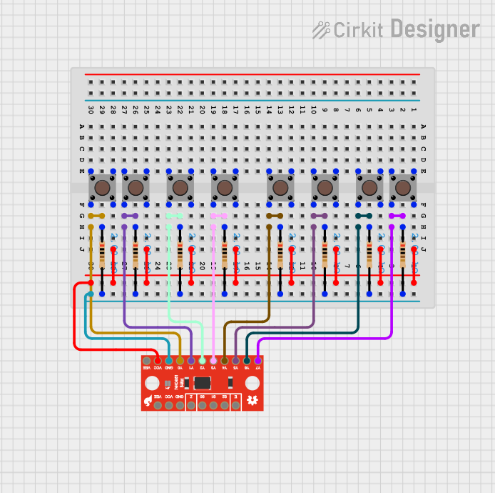
8-Channel Multiplexer with Pushbutton Inputs and Resistor Network
Image of 8 push pull buttons one mux: A project utilizing 3104 push button in a practical application
This circuit uses a SparkFun 74HC4051 8-Channel Multiplexer to read the states of eight pushbuttons. Each pushbutton is connected to a corresponding input channel on the multiplexer through a 2k Ohm resistor, allowing the multiplexer to sequentially read the button states and output them to a single data line.
Cirkit Designer LogoOpen Project in Cirkit Designer
Pushbutton Interface with General Purpose I/O Plug
Image of Assista GP IO: A project utilizing 3104 push button in a practical application
This circuit consists of a General Purpose Input/Output (GPIO) plug connected to four pushbuttons. Each pushbutton is wired to a unique input pin on the GPIO plug, allowing the state of each button (pressed or not pressed) to be detected individually. The common terminals of the pushbuttons are interconnected and likely serve as a ground or reference voltage connection.
Cirkit Designer LogoOpen Project in Cirkit Designer

Explore Projects Built with 3104 push button

Use Cirkit Designer to design, explore, and prototype these projects online. Some projects support real-time simulation. Click "Open Project" to start designing instantly!
Image of connect 4: A project utilizing 3104 push button in a practical application
Pushbutton-Controlled Interface with 40-Pin Connector and UBS Power Supply
This circuit consists of a 40-pin connector interfacing with four pushbuttons and a UBS power supply. The pushbuttons are used as inputs to the connector, which then relays the signals to other components or systems. The UBS power supply provides the necessary 24V power to the pushbuttons and the common ground for the circuit.
Cirkit Designer LogoOpen Project in Cirkit Designer
Image of 4 på rad: A project utilizing 3104 push button in a practical application
24V Pushbutton Control Interface with 40-Pin Connector
This circuit consists of a 24V power supply unit (PSU) connected to four pushbuttons. Each pushbutton is wired such that pressing it will send a 24V signal to a corresponding general-purpose input (GP In) on a 40-pin connector. The common return path for the pushbuttons is connected to the 0V of the PSU, which is also connected to the common (Com) for input pins on the 40-pin connector, completing the circuit for each button press.
Cirkit Designer LogoOpen Project in Cirkit Designer
Image of 8 push pull buttons one mux: A project utilizing 3104 push button in a practical application
8-Channel Multiplexer with Pushbutton Inputs and Resistor Network
This circuit uses a SparkFun 74HC4051 8-Channel Multiplexer to read the states of eight pushbuttons. Each pushbutton is connected to a corresponding input channel on the multiplexer through a 2k Ohm resistor, allowing the multiplexer to sequentially read the button states and output them to a single data line.
Cirkit Designer LogoOpen Project in Cirkit Designer
Image of Assista GP IO: A project utilizing 3104 push button in a practical application
Pushbutton Interface with General Purpose I/O Plug
This circuit consists of a General Purpose Input/Output (GPIO) plug connected to four pushbuttons. Each pushbutton is wired to a unique input pin on the GPIO plug, allowing the state of each button (pressed or not pressed) to be detected individually. The common terminals of the pushbuttons are interconnected and likely serve as a ground or reference voltage connection.
Cirkit Designer LogoOpen Project in Cirkit Designer

Technical Specifications

General Characteristics

  • Type: Momentary tactile push button
  • Model: 3104
  • Contact Type: Normally open (NO)
  • Actuation Force: Typically around 100-300 gf (grams force)
  • Life Expectancy: 100,000 to 1,000,000 cycles

Electrical Specifications

  • Maximum Voltage: 12V DC
  • Maximum Current: 50mA
  • Contact Resistance: < 50 mΩ initially
  • Insulation Resistance: > 100 MΩ at 500V DC

Pin Configuration and Descriptions

Pin Number Description
1 Terminal 1 (Contact)
2 Terminal 2 (Contact)

Note: The pins are usually interchangeable since the push button acts as a simple switch.

Usage Instructions

Integration into a Circuit

To use the 3104 push button in a circuit:

  1. Identify the two terminals on the push button.
  2. Connect one terminal to the input line where you want to control the current flow.
  3. Connect the second terminal to the output line that leads to the next component in the circuit.

Best Practices

  • Use a pull-up or pull-down resistor to ensure a stable state when the button is not pressed.
  • Avoid applying voltages higher than the maximum rating to prevent damage.
  • Ensure that the current through the button does not exceed the maximum current rating.

Example Code for Arduino UNO

Below is an example of how to use the 3104 push button with an Arduino UNO:

// Define the pin connected to the push button
const int buttonPin = 2;     
// Define the pin for the LED
const int ledPin =  13;      
// Variable for reading the push button status
int buttonState = 0;         

void setup() {
  // Initialize the LED pin as an output
  pinMode(ledPin, OUTPUT);      
  // Initialize the push button pin as an input
  pinMode(buttonPin, INPUT_PULLUP);  
}

void loop(){
  // Read the state of the push button value
  buttonState = digitalRead(buttonPin);

  // Check if the push button is pressed
  // if it is, the buttonState is LOW
  if (buttonState == LOW) {     
    // Turn on the LED
    digitalWrite(ledPin, HIGH);  
  } else {
    // Turn off the LED
    digitalWrite(ledPin, LOW);   
  }
}

Note: The INPUT_PULLUP mode enables the internal pull-up resistor, which is a best practice for push button circuits.

Troubleshooting and FAQs

Common Issues

  • Button does not respond: Ensure that the button is properly connected and that there are no loose connections.
  • Unstable button states: Debounce the button either through software or by using a hardware debounce circuit.
  • Button stuck in pressed state: Check for any physical obstructions or damage to the button mechanism.

FAQs

Q: Can I use the 3104 push button with AC voltage? A: No, the 3104 push button is rated for DC voltage only.

Q: How can I prevent "bouncing" when the button is pressed? A: Implement a debounce algorithm in your code or use a capacitor and resistor to create a hardware debounce circuit.

Q: Is it necessary to use a resistor with the push button? A: Yes, using a pull-up or pull-down resistor is recommended to ensure a defined logic level when the button is not pressed.

For further assistance, please refer to the manufacturer's datasheet or contact technical support.