
How to Use AAA Battery with PCB Clips: Examples, Pinouts, and Specs
 Design with AAA Battery with PCB Clips in Cirkit Designer
Introduction
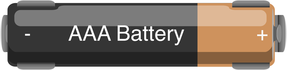
The AAA Battery with PCB Clips is a compact and efficient power source designed to securely hold AAA batteries while providing seamless electrical connections to a printed circuit board (PCB). This component is ideal for low-power electronic devices and prototyping applications, offering a reliable and reusable solution for powering circuits. Its integrated clips ensure a stable connection, making it suitable for both temporary and permanent installations.
Explore Projects Built with AAA Battery with PCB Clips
 Open Project in Cirkit Designer
 Open Project in Cirkit Designer
 Open Project in Cirkit Designer
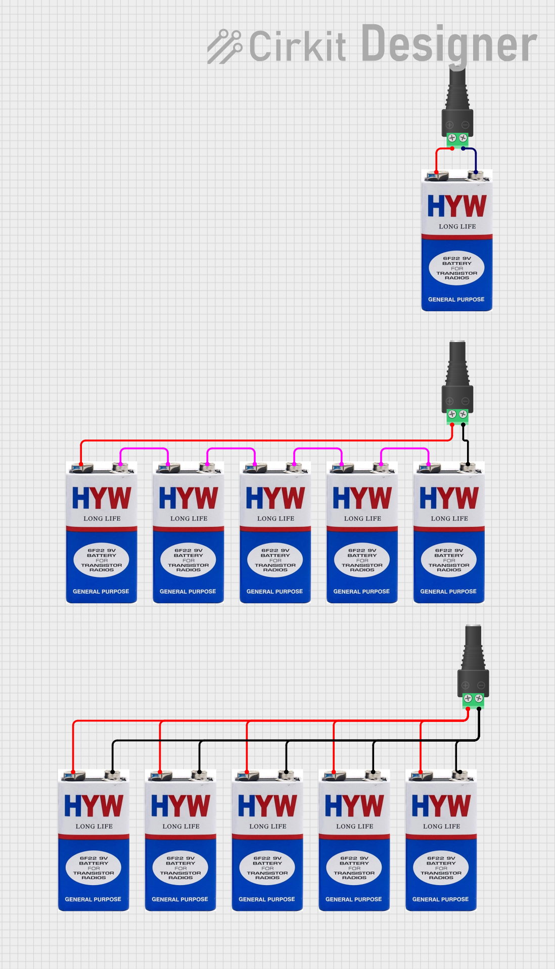 Open Project in Cirkit Designer
Explore Projects Built with AAA Battery with PCB Clips
Open Project in Cirkit DesignerOpen Project in Cirkit DesignerOpen Project in Cirkit DesignerOpen Project in Cirkit DesignerCommon Applications and Use Cases
- Powering small electronic devices such as remote controls, sensors, and LED circuits.
- Prototyping and testing circuits on breadboards or PCBs.
- Educational projects and DIY electronics.
- Backup power for low-power embedded systems.
Technical Specifications
Below are the key technical details for the AAA Battery with PCB Clips:
| Parameter | Specification |
|---|---|
| Battery Type | AAA (1.5V Alkaline or 1.2V NiMH) |
| Voltage Output | 1.2V to 1.5V per battery |
| Current Rating | Dependent on battery (typically 500mA to 1000mA) |
| Material | Plastic housing with metal clips |
| Dimensions | Varies (commonly ~50mm x 15mm x 10mm) |
| PCB Connection Type | Solderable metal clips |
| Operating Temperature | -20°C to 60°C |
| Weight | ~5g (without battery) |
Pin Configuration and Descriptions
The AAA Battery with PCB Clips typically has two connection points:
| Pin | Description |
|---|---|
| Positive (+) | Connects to the positive terminal of the battery. This pin provides the positive voltage output. |
| Negative (-) | Connects to the negative terminal of the battery. This pin serves as the ground or return path. |
Usage Instructions
How to Use the Component in a Circuit
- Insert the Battery: Place a AAA battery into the holder, ensuring the positive and negative terminals align with the markings on the holder.
- Connect to PCB: Solder the metal clips to the designated pads on your PCB. Ensure proper polarity to avoid damage to your circuit.
- Verify Connections: Use a multimeter to confirm the voltage output at the clips before powering your circuit.
- Integrate into Circuit: Connect the positive and negative terminals to the corresponding points in your circuit.
Important Considerations and Best Practices
- Polarity: Always double-check the polarity of the battery and connections to prevent reverse voltage, which can damage sensitive components.
- Current Limitations: Ensure the battery can supply sufficient current for your circuit. AAA batteries are suitable for low-power applications.
- Secure Mounting: If the holder is used in a mobile or vibrating environment, secure it with screws or adhesive to prevent disconnection.
- Battery Type: Use rechargeable NiMH batteries for eco-friendly applications or alkaline batteries for longer shelf life.
- Avoid Short Circuits: Ensure the metal clips do not accidentally short-circuit with other components on the PCB.
Example: Connecting to an Arduino UNO
The AAA Battery with PCB Clips can be used to power an Arduino UNO via its VIN pin. Below is an example circuit and code:
Circuit Setup
- Insert two AAA batteries into the holder (providing ~3V).
- Connect the positive terminal of the holder to the VIN pin of the Arduino UNO.
- Connect the negative terminal of the holder to the GND pin of the Arduino UNO.
Sample Code
// Blink an LED using power from AAA batteries
// Ensure the Arduino is powered via the VIN and GND pins

const int ledPin = 13; // Built-in LED pin on Arduino UNO

void setup() {
  pinMode(ledPin, OUTPUT); // Set the LED pin as an output
}

void loop() {
  digitalWrite(ledPin, HIGH); // Turn the LED on
  delay(1000);               // Wait for 1 second
  digitalWrite(ledPin, LOW);  // Turn the LED off
  delay(1000);               // Wait for 1 second
}
Note: Ensure the total voltage from the batteries is within the Arduino's acceptable input range (7-12V for VIN). Use a step-up converter if necessary.
Troubleshooting and FAQs
Common Issues Users Might Face
No Output Voltage:
- Cause: Battery inserted incorrectly or depleted.
- Solution: Check the battery orientation and replace the battery if necessary.
Loose Connection to PCB:
- Cause: Poor soldering or mechanical stress.
- Solution: Re-solder the clips securely and ensure the holder is mounted firmly.
Circuit Not Powering On:
- Cause: Insufficient voltage or current from the battery.
- Solution: Verify the battery's charge level and ensure it meets the circuit's power requirements.
Overheating Clips:
- Cause: Excessive current draw.
- Solution: Ensure the circuit's current draw is within the battery's capacity.
Solutions and Tips for Troubleshooting
- Use a multimeter to measure the voltage at the clips and confirm proper output.
- Inspect solder joints for cold soldering or cracks.
- If using rechargeable batteries, ensure they are fully charged before use.
- Avoid mixing old and new batteries, as this can lead to uneven discharge and reduced performance.
By following this documentation, you can effectively integrate the AAA Battery with PCB Clips into your electronic projects, ensuring reliable and efficient power delivery.