How to Use 2 Channel 5V 10A Relay Module with Optocoupler: Examples, Pinouts, and Specs
2 Channel 5V 10A Relay Module with Optocoupler Documentation
1. Introduction
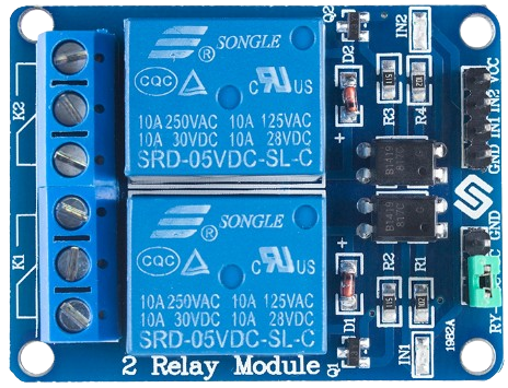
The 2 Channel 5V 10A Relay Module with Optocoupler is a versatile electronic component designed to control high-voltage devices using low-voltage signals. It features two independent relay channels, each capable of handling up to 10A at 250V AC or 30V DC. The module is equipped with optocouplers, which provide electrical isolation between the control circuit (e.g., a microcontroller) and the high-voltage load, ensuring safety and protecting sensitive components.
Common Applications
- Home automation (e.g., controlling lights, fans, or appliances)
- Industrial automation and control systems
- IoT projects for remote device control
- Robotics and mechatronics
- Switching high-power devices like motors, solenoids, or heaters
2. Technical Specifications
Key Technical Details
| Parameter | Specification |
|---|---|
| Operating Voltage | 5V DC |
| Relay Channels | 2 |
| Maximum Load (AC) | 250V AC @ 10A |
| Maximum Load (DC) | 30V DC @ 10A |
| Trigger Voltage | 3.3V to 5V (logic HIGH to activate relay) |
| Isolation | Optocoupler-based electrical isolation |
| Dimensions | ~50mm x 40mm x 18mm |
| Weight | ~30g |
| Indicator LEDs | Power LED and individual relay status LEDs |
| Control Signal Logic | Active LOW (relay activates when input pin is LOW) |
Pin Configuration and Descriptions
| Pin Name | Type | Description |
|---|---|---|
| VCC | Power Input | Connect to 5V DC power supply. Powers the relay module. |
| GND | Ground | Connect to the ground of the power supply or microcontroller. |
| IN1 | Control Input | Control signal for Relay 1. Active LOW (relay activates when this pin is LOW). |
| IN2 | Control Input | Control signal for Relay 2. Active LOW (relay activates when this pin is LOW). |
| COM1 | Load Terminal | Common terminal for Relay 1. Connect to the load circuit. |
| NO1 | Load Terminal | Normally Open terminal for Relay 1. Load is connected when relay is active. |
| NC1 | Load Terminal | Normally Closed terminal for Relay 1. Load is connected when relay is inactive. |
| COM2 | Load Terminal | Common terminal for Relay 2. Connect to the load circuit. |
| NO2 | Load Terminal | Normally Open terminal for Relay 2. Load is connected when relay is active. |
| NC2 | Load Terminal | Normally Closed terminal for Relay 2. Load is connected when relay is inactive. |
3. Usage Instructions
Connecting the Relay Module
- Power the Module: Connect the
VCCpin to a 5V DC power supply and theGNDpin to the ground of the same power supply or microcontroller. - Control Signals: Connect the
IN1andIN2pins to the digital output pins of a microcontroller (e.g., Arduino UNO). These pins will control the relays. - Load Connections:
- For each relay, connect the load circuit to the
COM,NO, andNCterminals as required:- Use
NO(Normally Open) if the load should be OFF by default and turn ON when the relay is activated. - Use
NC(Normally Closed) if the load should be ON by default and turn OFF when the relay is activated.
- Use
- For each relay, connect the load circuit to the
Example Circuit Diagram
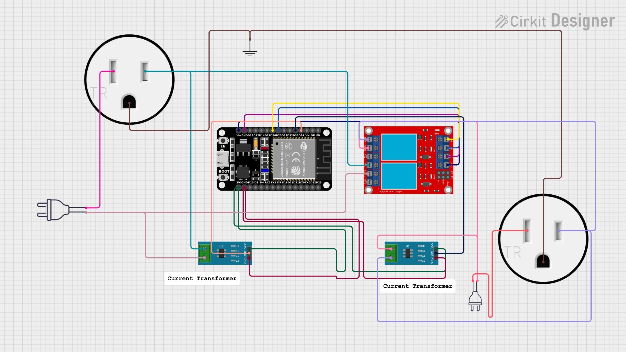
Below is an example of how to connect the relay module to an Arduino UNO and a 220V AC light bulb:
- Relay Module Connections:
VCC→ Arduino5VGND→ ArduinoGNDIN1→ Arduino Digital Pin 7IN2→ Arduino Digital Pin 8
- Load Connections:
- Connect one terminal of the light bulb to the
COM1terminal. - Connect the other terminal of the light bulb to the AC live wire.
- Connect the AC neutral wire to the
NO1terminal.
- Connect one terminal of the light bulb to the
Arduino Code Example
The following Arduino code demonstrates how to control the relays:
// Define relay control pins
const int relay1Pin = 7; // Relay 1 control pin
const int relay2Pin = 8; // Relay 2 control pin

void setup() {
  // Set relay pins as outputs
  pinMode(relay1Pin, OUTPUT);
  pinMode(relay2Pin, OUTPUT);

  // Initialize relays to OFF state (HIGH = relay off, LOW = relay on)
  digitalWrite(relay1Pin, HIGH);
  digitalWrite(relay2Pin, HIGH);
}

void loop() {
  // Turn Relay 1 ON
  digitalWrite(relay1Pin, LOW); // Activate relay 1
  delay(2000);                  // Wait for 2 seconds

  // Turn Relay 1 OFF
  digitalWrite(relay1Pin, HIGH); // Deactivate relay 1
  delay(2000);                   // Wait for 2 seconds

  // Turn Relay 2 ON
  digitalWrite(relay2Pin, LOW); // Activate relay 2
  delay(2000);                  // Wait for 2 seconds

  // Turn Relay 2 OFF
  digitalWrite(relay2Pin, HIGH); // Deactivate relay 2
  delay(2000);                   // Wait for 2 seconds
}
4. Important Considerations and Best Practices
- Power Supply: Ensure the relay module is powered by a stable 5V DC supply. Avoid exceeding the voltage rating.
- Electrical Isolation: The optocouplers provide isolation, but always exercise caution when working with high-voltage loads.
- Load Ratings: Do not exceed the maximum load ratings of 10A at 250V AC or 30V DC. Use a relay with higher ratings if needed.
- Inductive Loads: When switching inductive loads (e.g., motors), use a flyback diode or snubber circuit to protect the relay contacts from voltage spikes.
- Active LOW Logic: Remember that the relays are activated when the control pins (
IN1,IN2) are set to LOW.
5. Troubleshooting and FAQs
Common Issues and Solutions
| Issue | Possible Cause | Solution |
|---|---|---|
| Relay does not activate | Insufficient power supply | Ensure a stable 5V DC supply is connected. |
| Incorrect control signal logic | Ensure control pins are set to LOW to activate. | |
| Load does not turn ON/OFF | Incorrect load wiring | Verify connections to COM, NO, and NC. |
| Load exceeds relay rating | Use a relay with higher current/voltage rating. | |
| Relay module overheats | Continuous high current through relay contacts | Ensure load current is within the 10A limit. |
FAQs
Can I use this module with a 3.3V microcontroller?
- Yes, the module can be triggered with 3.3V logic signals, but ensure the
VCCpin is still powered with 5V.
- Yes, the module can be triggered with 3.3V logic signals, but ensure the
Can I control DC loads with this module?
- Yes, the module supports DC loads up to 30V at 10A.
What is the purpose of the optocoupler?
- The optocoupler electrically isolates the control circuit from the high-voltage load, protecting the microcontroller from potential damage.
Can I use both relays simultaneously?
- Yes, both relays can be used independently or simultaneously, provided the total load does not exceed the power supply capacity.
This documentation provides a comprehensive guide to using the 2 Channel 5V 10A Relay Module with Optocoupler. By following the instructions and best practices, you can safely and effectively integrate this module into your projects.
Explore Projects Built with 2 Channel 5V 10A Relay Module with Optocoupler


Explore Projects Built with 2 Channel 5V 10A Relay Module with Optocoupler