
How to Use STP16CP05: Examples, Pinouts, and Specs

 Design with STP16CP05 in Cirkit Designer
Introduction
The STP16CP05 is an N-channel MOSFET designed for high-speed switching applications. It features low on-resistance and high current handling capabilities, making it ideal for use in power management, motor control circuits, and other high-efficiency switching applications. Its robust design ensures reliable performance in demanding environments, making it a popular choice for engineers and hobbyists alike.
Explore Projects Built with STP16CP05
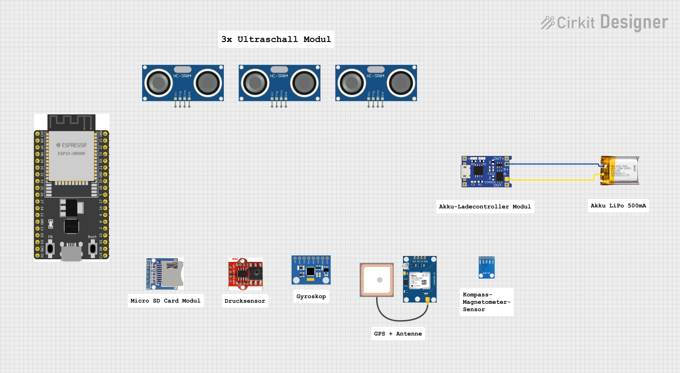 Open Project in Cirkit Designer
 Open Project in Cirkit Designer
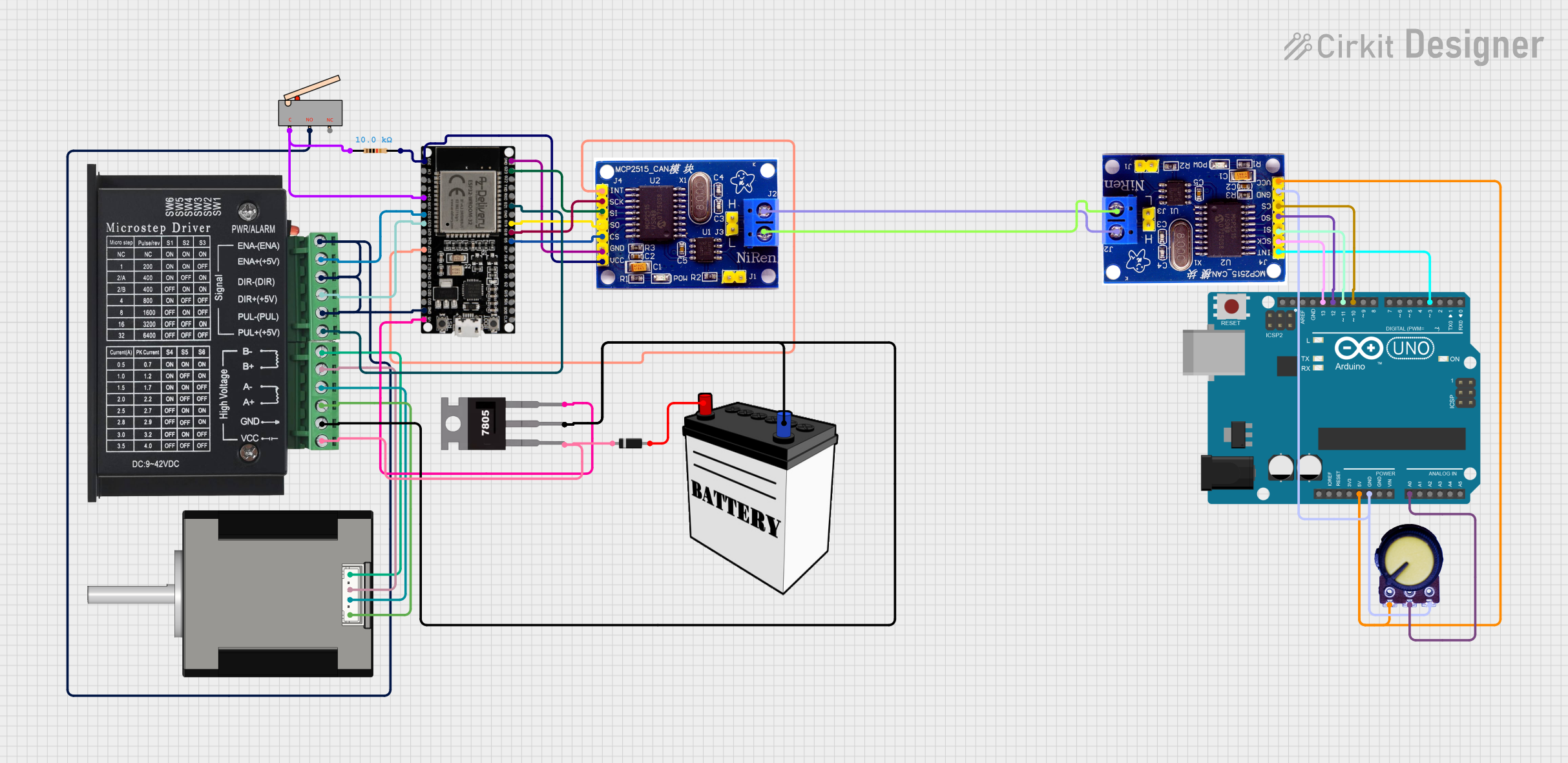 Open Project in Cirkit Designer
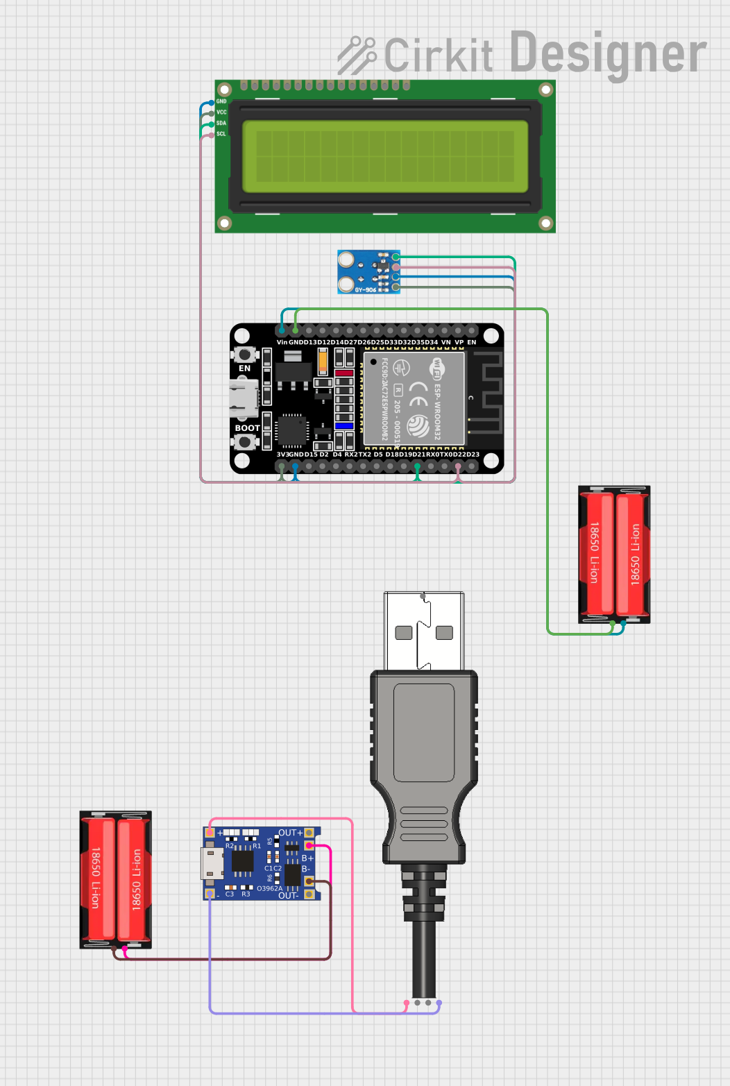 Open Project in Cirkit Designer
Explore Projects Built with STP16CP05
Open Project in Cirkit DesignerOpen Project in Cirkit DesignerOpen Project in Cirkit DesignerOpen Project in Cirkit DesignerCommon Applications
- Power management circuits
- Motor control systems
- DC-DC converters
- LED drivers
- High-speed switching applications
Technical Specifications
Below are the key technical details of the STP16CP05 MOSFET:
| Parameter | Value |
|---|---|
| Drain-Source Voltage (VDS) | 60V |
| Gate-Source Voltage (VGS) | ±20V |
| Continuous Drain Current (ID) | 16A |
| Pulsed Drain Current (IDM) | 64A |
| On-Resistance (RDS(on)) | 0.055Ω (typical) |
| Total Gate Charge (Qg) | 25nC |
| Power Dissipation (PD) | 45W |
| Operating Temperature Range | -55°C to +175°C |
| Package Type | TO-220 |
Pin Configuration
The STP16CP05 is typically available in a TO-220 package with three pins. The pin configuration is as follows:
| Pin Number | Pin Name | Description |
|---|---|---|
| 1 | Gate | Controls the MOSFET switching state |
| 2 | Drain | Current flows into this terminal |
| 3 | Source | Current flows out of this terminal |
Usage Instructions
How to Use the STP16CP05 in a Circuit
- Gate Control: Connect the gate pin to a control signal (e.g., from a microcontroller or driver circuit). Ensure the gate voltage (VGS) does not exceed ±20V.
- Drain-Source Connection: Connect the load between the drain and the positive supply voltage. The source pin should be connected to ground or the negative terminal of the power supply.
- Gate Resistor: Use a resistor (typically 10Ω to 100Ω) in series with the gate to limit inrush current and prevent damage to the MOSFET.
- Flyback Diode: For inductive loads (e.g., motors or relays), add a flyback diode across the load to protect the MOSFET from voltage spikes.
Example Circuit
Below is an example of using the STP16CP05 to control a DC motor with an Arduino UNO:
// Example: Controlling a DC motor with the STP16CP05 and Arduino UNO

const int motorPin = 9; // PWM pin connected to the MOSFET gate

void setup() {
  pinMode(motorPin, OUTPUT); // Set the motor pin as an output
}

void loop() {
  analogWrite(motorPin, 128); // Set motor speed to 50% (PWM value: 128)
  delay(5000);               // Run motor for 5 seconds
  analogWrite(motorPin, 0);  // Turn off the motor
  delay(5000);               // Wait for 5 seconds
}
Important Considerations
- Heat Dissipation: The STP16CP05 can handle high currents, but it may generate significant heat. Use a heatsink or active cooling to prevent overheating.
- Gate Drive Voltage: Ensure the gate drive voltage is sufficient to fully turn on the MOSFET (typically 10V for optimal performance).
- Protection: Add a TVS diode or zener diode across the gate-source terminals to protect against voltage spikes.
Troubleshooting and FAQs
Common Issues
MOSFET Overheating
- Cause: Insufficient cooling or excessive current.
- Solution: Use a heatsink or reduce the load current.
MOSFET Not Switching
- Cause: Insufficient gate drive voltage.
- Solution: Ensure the gate voltage is at least 10V for full enhancement.
Load Not Operating
- Cause: Incorrect wiring or damaged MOSFET.
- Solution: Double-check the circuit connections and test the MOSFET with a multimeter.
Voltage Spikes Damaging the MOSFET
- Cause: Inductive load without a flyback diode.
- Solution: Add a flyback diode across the load.
FAQs
Q: Can I drive the STP16CP05 directly from a 3.3V microcontroller?
A: No, the STP16CP05 requires a gate voltage of at least 10V for optimal performance. Use a gate driver circuit to step up the voltage.
Q: What is the maximum current the STP16CP05 can handle?
A: The MOSFET can handle up to 16A continuously and 64A in pulsed mode, provided adequate cooling is used.
Q: How do I test if the MOSFET is working?
A: Use a multimeter in diode mode. Check for continuity between the drain and source when the gate is activated. There should be no continuity when the gate is not activated.
By following this documentation, you can effectively integrate the STP16CP05 into your electronic projects and troubleshoot common issues with ease.