How to Use GM12864-59N: Examples, Pinouts, and Specs
Introduction
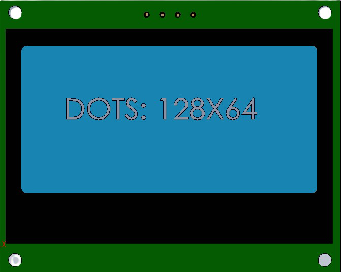
The GM12864-59N is a graphic LCD module with a resolution of 128x64 pixels, designed for displaying both text and graphics in embedded systems. This versatile display module is widely used in applications such as industrial control panels, handheld devices, and DIY electronics projects. It supports both SPI and parallel communication protocols, making it compatible with a variety of microcontrollers and development boards.
Explore Projects Built with GM12864-59N


Explore Projects Built with GM12864-59N
Common Applications and Use Cases
- Industrial control systems for displaying real-time data
- Handheld devices requiring graphical user interfaces
- DIY electronics projects and prototyping
- Embedded systems with text and graphical display needs
- Home automation systems for status monitoring
Technical Specifications
The GM12864-59N is a robust and reliable display module with the following key specifications:
| Parameter | Value |
|---|---|
| Display Resolution | 128x64 pixels |
| Operating Voltage | 5V DC |
| Communication Protocols | SPI or Parallel |
| Backlight | LED (white or blue) |
| Operating Temperature | -20°C to +70°C |
| Storage Temperature | -30°C to +80°C |
| Dimensions | 93mm x 70mm x 13mm |
| Viewing Area | 72mm x 40mm |
| Controller IC | ST7920 or equivalent |
Pin Configuration and Descriptions
The GM12864-59N has a 20-pin interface. The pin configuration is as follows:
| Pin Number | Pin Name | Description |
|---|---|---|
| 1 | VSS | Ground (0V) |
| 2 | VDD | Power supply (5V) |
| 3 | VO | Contrast adjustment (connect to a potentiometer) |
| 4 | RS | Register Select (Command/Data selection) |
| 5 | R/W | Read/Write control (High for Read, Low for Write) |
| 6 | E | Enable signal (used to latch data) |
| 7-14 | DB0-DB7 | Data bus lines (used in parallel mode) |
| 15 | PSB | Interface selection (High for Parallel, Low for SPI) |
| 16 | NC | No connection (leave unconnected) |
| 17 | RST | Reset signal (active low) |
| 18 | VOUT | Voltage output for internal use (connect to a capacitor for stability) |
| 19 | BLA | Backlight anode (connect to 5V via a current-limiting resistor) |
| 20 | BLK | Backlight cathode (connect to ground) |
Usage Instructions
How to Use the GM12864-59N in a Circuit
- Power Supply: Connect the VDD pin to a 5V power source and the VSS pin to ground.
- Contrast Adjustment: Connect the VO pin to the wiper of a 10kΩ potentiometer. Connect one end of the potentiometer to VDD and the other to VSS. Adjust the potentiometer to set the display contrast.
- Communication Mode: Use the PSB pin to select the communication protocol:
- High (5V): Parallel mode
- Low (0V): SPI mode
- Backlight: Connect the BLA pin to 5V through a suitable current-limiting resistor (e.g., 220Ω). Connect the BLK pin to ground.
- Microcontroller Interface: Connect the data and control pins (RS, R/W, E, DB0-DB7 for parallel mode or RS, R/W, E for SPI mode) to the corresponding pins on your microcontroller.
Important Considerations and Best Practices
- Ensure the power supply is stable and within the specified range (5V ±5%).
- Use decoupling capacitors (e.g., 0.1µF) near the power pins to reduce noise.
- For SPI mode, ensure the PSB pin is tied to ground and unused data pins (DB0-DB7) are left unconnected.
- Avoid excessive backlight current to prevent overheating. Use a resistor to limit the current.
- Handle the module carefully to avoid damaging the LCD glass or flex cable.
Example: Connecting to an Arduino UNO (SPI Mode)
Below is an example of how to connect and program the GM12864-59N in SPI mode with an Arduino UNO:
Wiring Diagram
| GM12864-59N Pin | Arduino UNO Pin |
|---|---|
| VSS | GND |
| VDD | 5V |
| VO | Potentiometer (middle pin) |
| RS | Pin 9 |
| R/W | GND |
| E | Pin 10 |
| PSB | GND |
| RST | Pin 8 |
| BLA | 5V (via 220Ω resistor) |
| BLK | GND |
Arduino Code
#include <U8g2lib.h>

// Initialize the display in SPI mode
U8G2_ST7920_128X64_F_SW_SPI u8g2(U8G2_R0, /* clock=*/ 13, /* data=*/ 11,
                                 /* cs=*/ 10, /* reset=*/ 8);

void setup() {
  u8g2.begin(); // Initialize the display
}

void loop() {
  u8g2.clearBuffer(); // Clear the display buffer
  u8g2.setFont(u8g2_font_ncenB08_tr); // Set font
  u8g2.drawStr(0, 10, "Hello, GM12864!"); // Draw text
  u8g2.sendBuffer(); // Send buffer to display
  delay(1000); // Wait for 1 second
}
Troubleshooting and FAQs
Common Issues and Solutions
No Display Output:
- Verify the power connections (VDD and VSS).
- Check the contrast adjustment (VO pin and potentiometer).
- Ensure the backlight is properly connected.
Flickering or Unstable Display:
- Add decoupling capacitors (e.g., 0.1µF) near the power pins.
- Verify the communication protocol selection (PSB pin).
Incorrect or Garbled Text/Graphics:
- Check the wiring of the data and control pins.
- Ensure the microcontroller code matches the selected communication protocol.
Backlight Not Working:
- Verify the current-limiting resistor value.
- Check the BLA and BLK connections.
FAQs
Q: Can I use the GM12864-59N with a 3.3V microcontroller?
A: Yes, but you will need a level shifter to convert the 3.3V logic signals to 5V.
Q: What is the typical current consumption of the module?
A: The module typically consumes around 20-30mA, excluding the backlight.
Q: Can I use the module in bright sunlight?
A: The GM12864-59N is not sunlight-readable. For outdoor use, consider a display with higher brightness or contrast.
Q: How do I clean the display surface?
A: Use a soft, lint-free cloth. Avoid using harsh chemicals or abrasive materials.