
How to Use Arduino Nano RP2040 Connect: Examples, Pinouts, and Specs
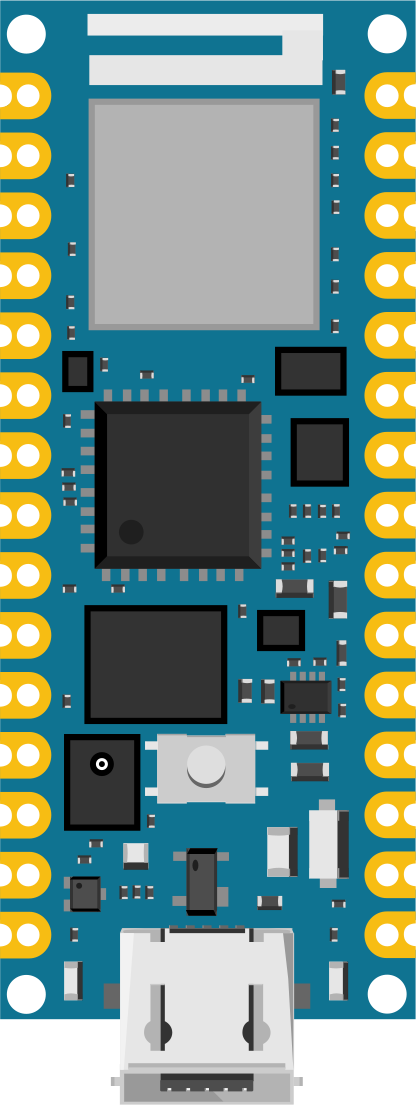
 Design with Arduino Nano RP2040 Connect in Cirkit Designer
Introduction
The Arduino Nano RP2040 Connect is a compact microcontroller board developed by Arduino, featuring the powerful RP2040 chip. It is equipped with built-in Wi-Fi and Bluetooth connectivity, making it an excellent choice for IoT (Internet of Things) projects, prototyping, and edge computing applications. This board combines the flexibility of the RP2040 microcontroller with the convenience of Arduino's ecosystem, offering a seamless development experience for both beginners and advanced users.
Explore Projects Built with Arduino Nano RP2040 Connect
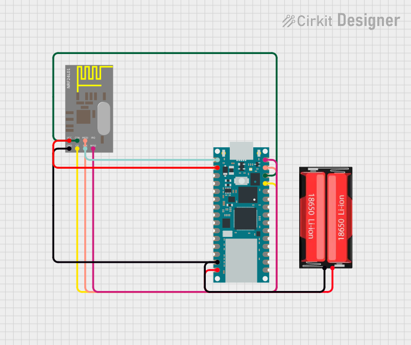 Open Project in Cirkit Designer
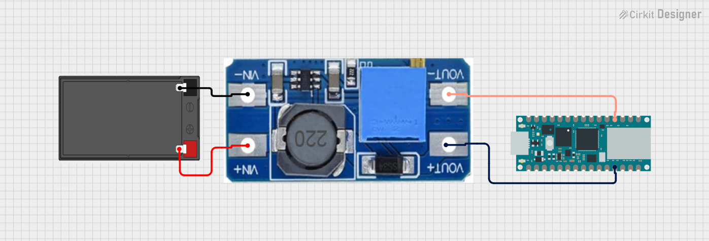 Open Project in Cirkit Designer
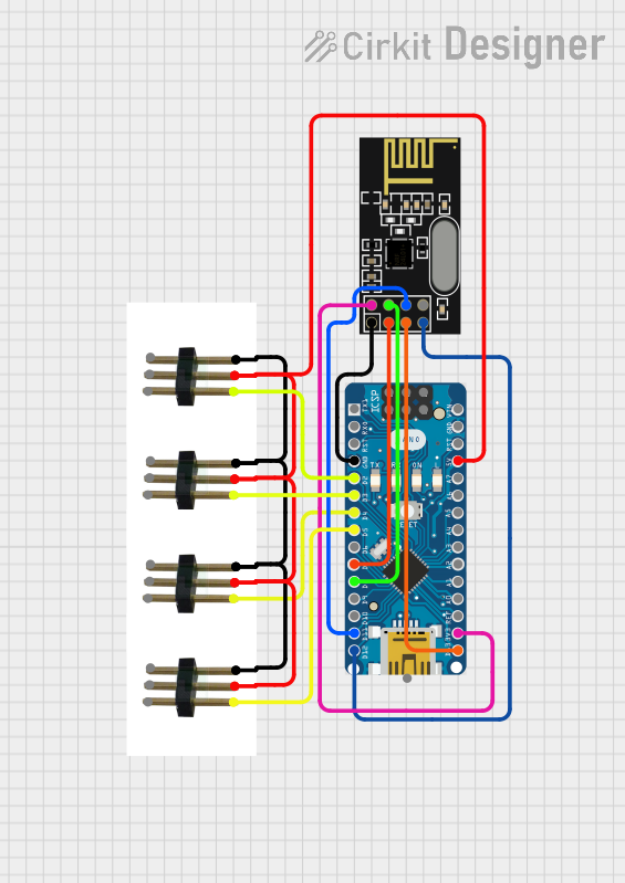 Open Project in Cirkit Designer
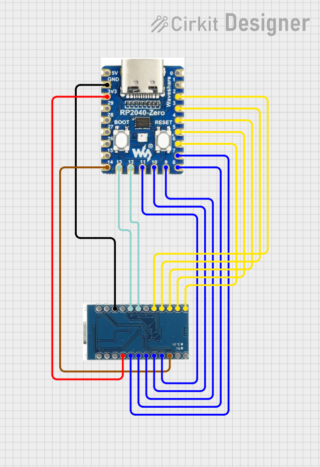 Open Project in Cirkit Designer
Explore Projects Built with Arduino Nano RP2040 Connect
Open Project in Cirkit DesignerOpen Project in Cirkit DesignerOpen Project in Cirkit DesignerOpen Project in Cirkit DesignerCommon Applications and Use Cases
- IoT devices and smart home automation
- Wireless sensor networks
- Data logging and remote monitoring
- Machine learning at the edge
- Robotics and automation projects
- Prototyping and educational purposes
Technical Specifications
The Arduino Nano RP2040 Connect is packed with features that make it versatile and powerful. Below are its key technical details:
Key Technical Details
| Specification | Value |
|---|---|
| Microcontroller | RP2040 (Dual-core ARM Cortex-M0+) |
| Clock Speed | 133 MHz |
| Flash Memory | 16 MB |
| SRAM | 264 KB |
| Connectivity | Wi-Fi (2.4 GHz), Bluetooth 4.2 |
| USB Interface | Micro USB (USB 1.1) |
| Operating Voltage | 3.3V |
| Input Voltage (VIN) | 5V |
| Digital I/O Pins | 20 |
| PWM Pins | 20 |
| Analog Input Pins | 8 |
| Communication Interfaces | UART, I2C, SPI |
| Onboard Sensors | IMU (LSM6DSOX), Microphone (MP34DT05) |
| Dimensions | 45 x 18 mm |
Pin Configuration and Descriptions
The Arduino Nano RP2040 Connect has a total of 28 pins, including power, digital, analog, and communication pins. Below is the pinout description:
| Pin Number | Pin Name | Description |
|---|---|---|
| 1 | VIN | Input voltage (5V) for powering the board |
| 2 | GND | Ground |
| 3 | 3.3V | Regulated 3.3V output |
| 4-11 | D0-D7 | Digital I/O pins |
| 12-19 | A0-A7 | Analog input pins |
| 20 | TX | UART Transmit |
| 21 | RX | UART Receive |
| 22 | SCL | I2C Clock |
| 23 | SDA | I2C Data |
| 24 | MOSI | SPI Master Out Slave In |
| 25 | MISO | SPI Master In Slave Out |
| 26 | SCK | SPI Clock |
| 27 | RST | Reset |
| 28 | IOREF | Reference voltage for I/O pins |
Usage Instructions
The Arduino Nano RP2040 Connect is easy to use and integrates seamlessly with the Arduino IDE. Below are the steps and best practices for using this board in your projects.
How to Use the Component in a Circuit
Powering the Board:
- Use the Micro USB port to power the board and upload code.
- Alternatively, supply 5V to the VIN pin for external power.
Connecting Sensors and Actuators:
- Use the digital pins (D0-D7) for digital sensors and actuators.
- Use the analog pins (A0-A7) for analog sensors.
Wi-Fi and Bluetooth Setup:
- Use the onboard Wi-Fi module for wireless communication.
- Pair the board with Bluetooth-enabled devices for short-range communication.
Programming the Board:
- Install the Arduino IDE and add the "Arduino Mbed OS RP2040 Boards" package.
- Select "Arduino Nano RP2040 Connect" as the board in the Tools menu.
- Write your code and upload it via the Micro USB port.
Important Considerations and Best Practices
- Ensure the input voltage does not exceed 5V to avoid damaging the board.
- Use level shifters when interfacing with 5V logic devices, as the board operates at 3.3V.
- Avoid drawing excessive current from the 3.3V pin to prevent overheating.
- Use proper libraries for onboard sensors (e.g., LSM6DSOX and MP34DT05) to simplify development.
Example Code for Arduino Nano RP2040 Connect
Below is an example of how to connect the board to a Wi-Fi network and send data to a server:
#include <WiFiNINA.h> // Include Wi-Fi library for Nano RP2040 Connect

// Replace with your network credentials
const char* ssid = "Your_SSID";
const char* password = "Your_PASSWORD";

void setup() {
  Serial.begin(9600); // Initialize serial communication
  while (!Serial);

  // Connect to Wi-Fi
  Serial.print("Connecting to Wi-Fi...");
  WiFi.begin(ssid, password);

  while (WiFi.status() != WL_CONNECTED) {
    delay(1000);
    Serial.print(".");
  }

  Serial.println("\nConnected to Wi-Fi!");
  Serial.print("IP Address: ");
  Serial.println(WiFi.localIP());
}

void loop() {
  // Add your main code here
}
Troubleshooting and FAQs
Common Issues Users Might Face
Board Not Detected by Arduino IDE:
- Ensure the correct board and port are selected in the Tools menu.
- Install the "Arduino Mbed OS RP2040 Boards" package if not already installed.
Wi-Fi Connection Fails:
- Double-check the SSID and password.
- Ensure the Wi-Fi network is within range and operational.
Code Upload Fails:
- Press the reset button twice to enter bootloader mode.
- Check the USB cable for data transfer capability.
Sensors Not Responding:
- Verify the connections and ensure the correct libraries are installed.
- Check for proper initialization in the code.
Solutions and Tips for Troubleshooting
- Use the Serial Monitor to debug and print error messages.
- Update the firmware of the Wi-Fi module using the Arduino IDE if connectivity issues persist.
- Refer to the official Arduino documentation for additional support and resources.
By following this documentation, you can effectively utilize the Arduino Nano RP2040 Connect for a wide range of applications, from simple projects to advanced IoT solutions.