How to Use ESP32 S3: Examples, Pinouts, and Specs
Introduction
The ESP32 S3 is a powerful microcontroller with integrated Wi-Fi and Bluetooth capabilities, designed specifically for Internet of Things (IoT) applications. It features a dual-core processor, ample GPIO pins, and support for various peripherals, making it ideal for complex projects requiring wireless connectivity. The ESP32 S3 is widely used in smart home devices, wearable electronics, industrial automation, and other applications where wireless communication and efficient processing are essential.
Explore Projects Built with ESP32 S3


Explore Projects Built with ESP32 S3
Common Applications and Use Cases
- Smart home devices (e.g., smart lights, thermostats)
- Wearable electronics
- Industrial IoT systems
- Wireless sensor networks
- Robotics and automation
- Real-time data monitoring and logging
Technical Specifications
The ESP32 S3 offers a robust set of features and specifications that make it a versatile choice for a wide range of applications.
Key Technical Details
- Processor: Dual-core Xtensa LX7, up to 240 MHz
- Wireless Connectivity: Wi-Fi 802.11 b/g/n and Bluetooth 5.0 (LE)
- Flash Memory: Up to 16 MB
- SRAM: 512 KB
- GPIO Pins: 45 (configurable for various functions)
- Operating Voltage: 3.0V to 3.6V
- Power Consumption: Ultra-low power in deep sleep mode (~10 µA)
- Peripherals: SPI, I2C, UART, ADC, DAC, PWM, and more
- Temperature Range: -40°C to +85°C
- Package: QFN48
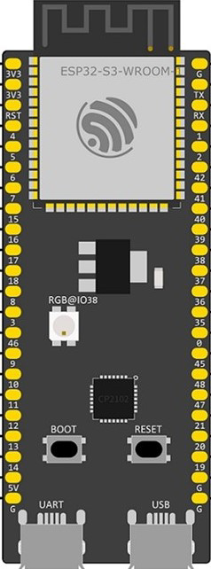
Pin Configuration and Descriptions
The ESP32 S3 has a rich set of GPIO pins and peripherals. Below is a table summarizing the key pins and their functions.
| Pin Name | Function | Description |
|---|---|---|
| GPIO0 | Input/Output, Boot Mode Select | Used for boot mode selection during startup. |
| GPIO1 | UART TX | Transmit pin for UART communication. |
| GPIO2 | Input/Output | General-purpose I/O pin. |
| GPIO3 | UART RX | Receive pin for UART communication. |
| GPIO4 | PWM, ADC | Can be used for Pulse Width Modulation or Analog-to-Digital Conversion. |
| GPIO12-15 | SPI | SPI interface pins for communication with external devices. |
| GPIO21 | I2C SDA | Data line for I2C communication. |
| GPIO22 | I2C SCL | Clock line for I2C communication. |
| GPIO25-26 | DAC | Digital-to-Analog Converter pins. |
| GPIO32-39 | ADC | Analog-to-Digital Converter pins for reading analog signals. |
| EN | Enable | Resets the chip when pulled low. |
| 3V3 | Power Supply | Provides 3.3V power to the board. |
| GND | Ground | Ground connection. |
Note: Some GPIO pins have specific restrictions or are reserved for internal functions. Refer to the ESP32 S3 datasheet for detailed pin multiplexing information.
Usage Instructions
The ESP32 S3 can be used in a variety of circuits and projects. Below are the steps to get started and important considerations.
How to Use the ESP32 S3 in a Circuit
- Power Supply: Ensure the ESP32 S3 is powered with a stable 3.3V supply. Avoid exceeding the maximum voltage of 3.6V.
- Boot Mode: Connect GPIO0 to GND during startup to enter bootloader mode for programming.
- Peripherals: Connect peripherals (e.g., sensors, actuators) to the appropriate GPIO pins. Use pull-up or pull-down resistors as needed.
- Programming: Use the Arduino IDE or ESP-IDF (Espressif IoT Development Framework) to write and upload code to the ESP32 S3.
Example: Connecting to Wi-Fi with Arduino IDE
Below is an example of how to connect the ESP32 S3 to a Wi-Fi network using the Arduino IDE.
#include <WiFi.h> // Include the Wi-Fi library

// Replace with your network credentials
const char* ssid = "Your_SSID";       // Your Wi-Fi network name
const char* password = "Your_PASSWORD"; // Your Wi-Fi network password

void setup() {
  Serial.begin(115200); // Initialize serial communication at 115200 baud
  WiFi.begin(ssid, password); // Start connecting to Wi-Fi

  Serial.print("Connecting to Wi-Fi");
  while (WiFi.status() != WL_CONNECTED) {
    delay(500); // Wait for connection
    Serial.print(".");
  }
  Serial.println("\nConnected to Wi-Fi!");
  Serial.print("IP Address: ");
  Serial.println(WiFi.localIP()); // Print the device's IP address
}

void loop() {
  // Add your main code here
}
Important Considerations and Best Practices
- Voltage Levels: Ensure all connected devices operate at 3.3V logic levels to avoid damaging the ESP32 S3.
- Deep Sleep Mode: Use deep sleep mode to conserve power in battery-powered applications.
- Antenna Placement: For optimal Wi-Fi and Bluetooth performance, ensure the onboard antenna is not obstructed by metal or other materials.
- Firmware Updates: Keep the ESP32 S3 firmware updated to benefit from the latest features and bug fixes.
Troubleshooting and FAQs
Common Issues and Solutions
Issue: The ESP32 S3 does not connect to Wi-Fi.
- Solution: Double-check the SSID and password. Ensure the Wi-Fi network is operational and within range.
Issue: The board is not detected by the computer.
- Solution: Install the correct USB-to-serial driver for the ESP32 S3. Use a high-quality USB cable.
Issue: GPIO pins are not functioning as expected.
- Solution: Verify the pin configuration in your code. Check for conflicts with other peripherals.
Issue: High power consumption in battery-powered applications.
- Solution: Use deep sleep mode and disable unused peripherals to reduce power consumption.
FAQs
Q: Can the ESP32 S3 be programmed using the Arduino IDE?
A: Yes, the ESP32 S3 is fully compatible with the Arduino IDE. Install the ESP32 board package to get started.Q: What is the maximum range of the ESP32 S3's Wi-Fi?
A: The range depends on environmental factors but typically extends up to 100 meters in open spaces.Q: Can I use the ESP32 S3 for Bluetooth audio applications?
A: Yes, the ESP32 S3 supports Bluetooth 5.0, which can be used for audio streaming and other Bluetooth applications.Q: How do I update the firmware on the ESP32 S3?
A: Use the ESP-IDF or a compatible flashing tool to upload the latest firmware to the device.
By following this documentation, you can effectively utilize the ESP32 S3 in your projects and troubleshoot common issues.