How to Use CTS A500 Push-Pull: Examples, Pinouts, and Specs
Introduction
The CTS A500 Push-Pull is a high-quality potentiometer designed specifically for audio applications. It features a dual-gang configuration, enabling simultaneous control of two independent signals. This makes it an excellent choice for applications requiring precise and synchronized adjustments, such as mixing consoles, guitar amplifiers, and other professional audio equipment. Additionally, the push-pull functionality allows for switching between different circuit configurations, adding versatility to its use.
Explore Projects Built with CTS A500 Push-Pull
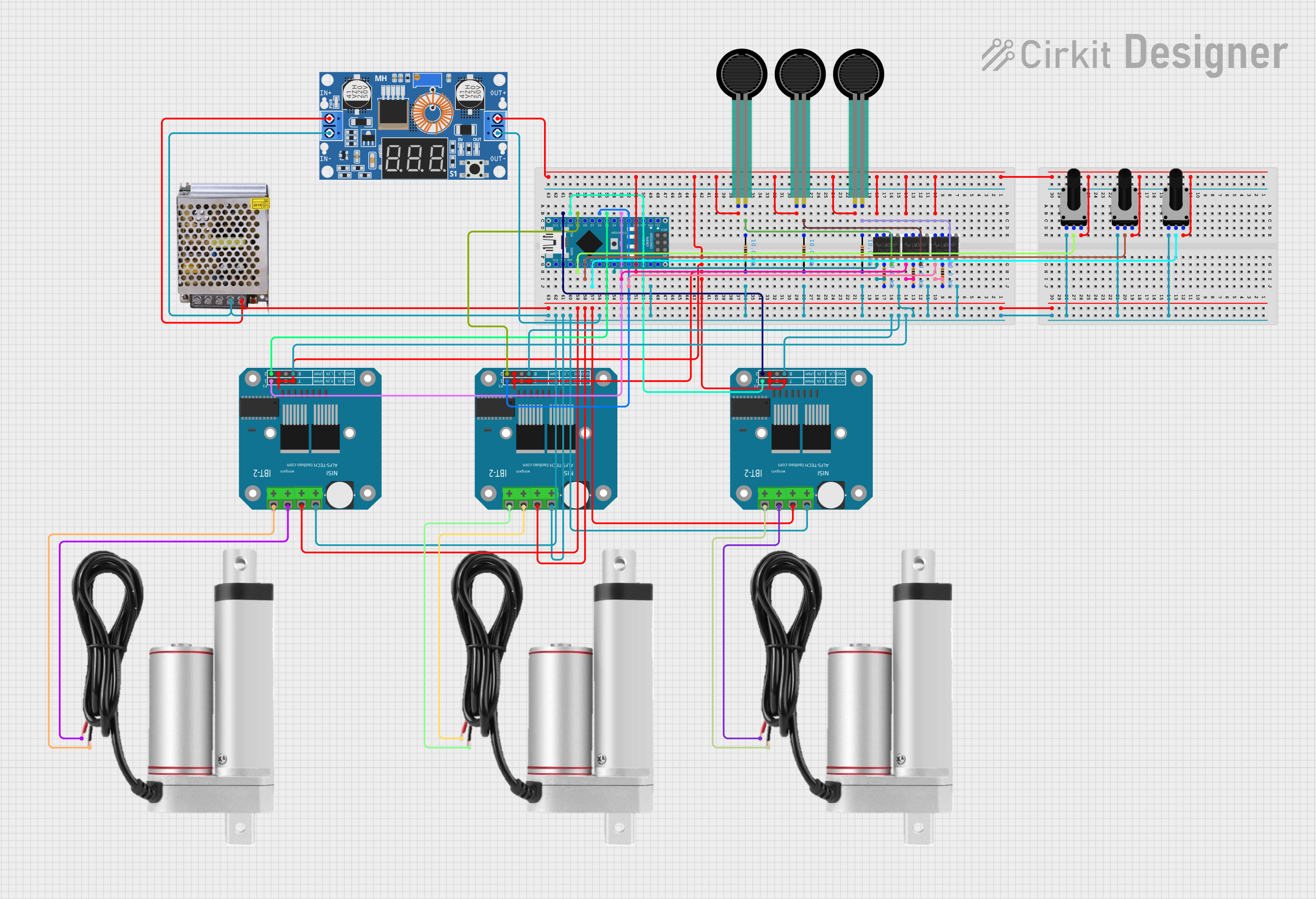

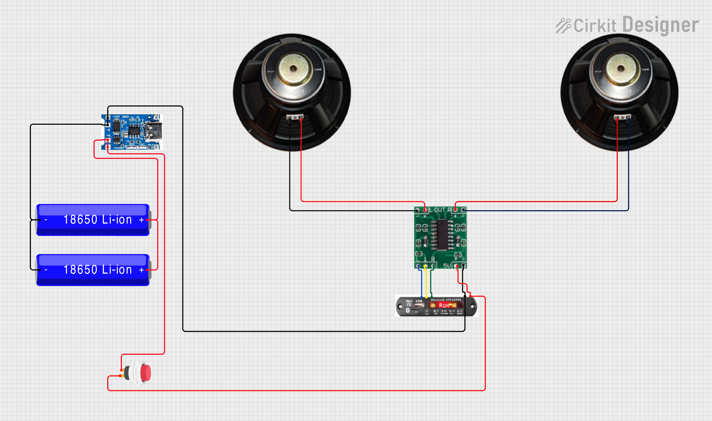

Explore Projects Built with CTS A500 Push-Pull
Common Applications
- Guitar amplifiers for tone and volume control
- Audio mixing consoles
- Hi-Fi audio systems
- Signal processing equipment
- Custom audio projects requiring dual-gang potentiometers with switching capabilities
Technical Specifications
Key Technical Details
| Parameter | Value |
|---|---|
| Manufacturer | CTS |
| Model Number | A500 Push-Pull |
| Resistance Value | 500 kΩ |
| Taper Type | Audio (Logarithmic) |
| Configuration | Dual-gang with push-pull switch |
| Power Rating | 0.25 W (per gang) |
| Operating Temperature | -10°C to +70°C |
| Shaft Diameter | 6 mm |
| Shaft Length | 18 mm |
| Mounting Style | Panel mount |
| Switch Type | SPDT (Single Pole Double Throw) |
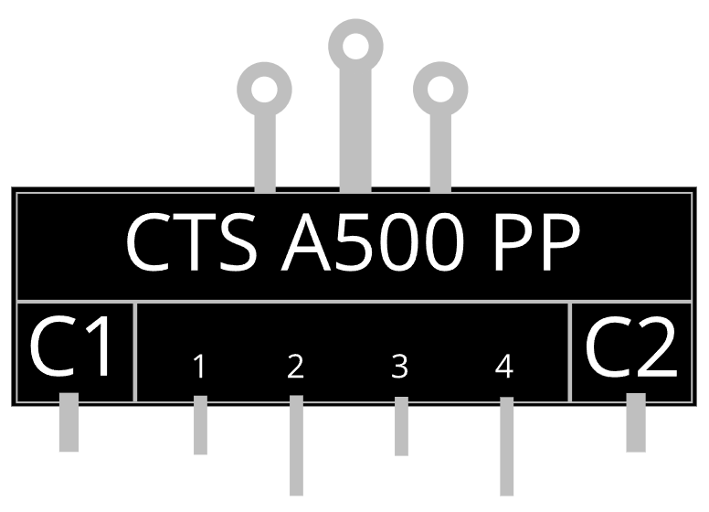
Pin Configuration and Descriptions
The CTS A500 Push-Pull potentiometer has a total of 9 pins: 6 for the dual-gang potentiometer and 3 for the push-pull switch.
Potentiometer Pins
| Pin Number | Description |
|---|---|
| 1 (Gang 1) | Input terminal for the first gang |
| 2 (Gang 1) | Wiper terminal for the first gang |
| 3 (Gang 1) | Output terminal for the first gang |
| 1 (Gang 2) | Input terminal for the second gang |
| 2 (Gang 2) | Wiper terminal for the second gang |
| 3 (Gang 2) | Output terminal for the second gang |
Push-Pull Switch Pins
| Pin Number | Description |
|---|---|
| 1 | Common terminal |
| 2 | Normally closed (NC) terminal |
| 3 | Normally open (NO) terminal |
Usage Instructions
How to Use the Component in a Circuit
Potentiometer Connections:
- Connect the input terminal of each gang to the signal source.
- Connect the wiper terminal to the desired output or load.
- Connect the output terminal to ground or the reference voltage, depending on the circuit design.
Push-Pull Switch Connections:
- Use the common terminal as the input for the switch.
- Connect the NC terminal to the circuit that should be active when the switch is not pulled.
- Connect the NO terminal to the circuit that should be active when the switch is pulled.
Mounting:
- Secure the potentiometer to the panel using the provided nut and washer.
- Ensure the shaft is aligned properly for smooth operation.
Wiring Example:
- For a guitar amplifier, the potentiometer can be used to control volume (gang 1) and tone (gang 2), while the push-pull switch can toggle between two different tone circuits.
Important Considerations and Best Practices
- Avoid exceeding the power rating of 0.25 W per gang to prevent damage.
- Use shielded cables for audio applications to minimize noise and interference.
- Ensure proper grounding to avoid hum or unwanted noise in audio circuits.
- When soldering, avoid applying excessive heat to the pins to prevent damage to the internal components.
Arduino UNO Example Code
The CTS A500 Push-Pull potentiometer can be used with an Arduino UNO for basic signal reading and switch detection. Below is an example code snippet:
// Define pin connections
const int potPin1 = A0; // First gang wiper connected to A0
const int potPin2 = A1; // Second gang wiper connected to A1
const int switchPin = 2; // Push-pull switch common terminal to digital pin 2

void setup() {
  // Initialize serial communication for debugging
  Serial.begin(9600);

  // Configure switch pin as input with pull-up resistor
  pinMode(switchPin, INPUT_PULLUP);
}

void loop() {
  // Read potentiometer values
  int potValue1 = analogRead(potPin1); // Read first gang
  int potValue2 = analogRead(potPin2); // Read second gang

  // Read switch state
  bool switchState = digitalRead(switchPin); // LOW = pulled, HIGH = not pulled

  // Print values to the serial monitor
  Serial.print("Potentiometer 1: ");
  Serial.print(potValue1);
  Serial.print(" | Potentiometer 2: ");
  Serial.print(potValue2);
  Serial.print(" | Switch State: ");
  Serial.println(switchState ? "Not Pulled" : "Pulled");

  // Add a small delay for stability
  delay(100);
}
Notes:
- Connect the potentiometer wiper terminals to the analog input pins (A0, A1) of the Arduino.
- The push-pull switch common terminal connects to digital pin 2, while the NC and NO terminals can be left unconnected for basic detection.
Troubleshooting and FAQs
Common Issues and Solutions
No Signal Output:
- Ensure all connections are secure and correctly wired.
- Verify that the potentiometer is not damaged or worn out.
Noise or Interference in Audio:
- Use shielded cables and proper grounding to reduce noise.
- Check for loose connections or cold solder joints.
Switch Not Functioning:
- Verify the switch connections and ensure the common terminal is properly wired.
- Test the switch with a multimeter to confirm continuity.
Inconsistent Potentiometer Operation:
- Clean the potentiometer with contact cleaner to remove dust or debris.
- Replace the potentiometer if wear or damage is evident.
FAQs
Q: Can the CTS A500 Push-Pull be used for non-audio applications?
A: Yes, while it is optimized for audio, it can be used in any circuit requiring a dual-gang potentiometer with a push-pull switch.
Q: What is the difference between audio and linear taper?
A: Audio taper potentiometers change resistance logarithmically, matching the human ear's perception of sound, while linear taper potentiometers change resistance uniformly.
Q: How do I know if the push-pull switch is engaged?
A: The switch state can be detected by checking the continuity between the common terminal and the NC or NO terminal.
Q: Can I replace a single-gang potentiometer with the CTS A500 Push-Pull?
A: Yes, but only one gang will be used, and the push-pull switch functionality may remain unused unless required.