How to Use Solar panel : Examples, Pinouts, and Specs
Introduction
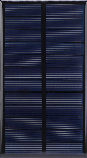
The AZAVA 1 solar panel is a high-efficiency photovoltaic device designed to convert sunlight into electrical energy. It is an eco-friendly and sustainable energy source, ideal for powering small electronic devices, charging batteries, or integrating into larger renewable energy systems. With its compact design and reliable performance, the AZAVA 1 solar panel is suitable for both hobbyist projects and professional applications.
Explore Projects Built with Solar panel
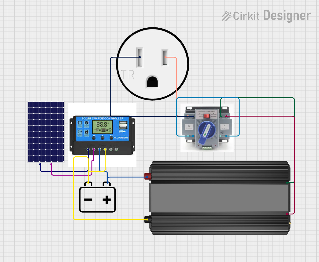

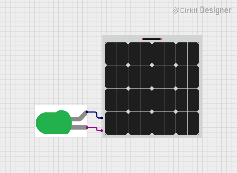

Explore Projects Built with Solar panel
Common Applications and Use Cases
- Charging small batteries (e.g., Li-ion, NiMH)
- Powering low-power IoT devices and sensors
- Solar-powered Arduino or Raspberry Pi projects
- Portable solar chargers for mobile devices
- Educational and experimental renewable energy projects
Technical Specifications
The following table outlines the key technical details of the AZAVA 1 solar panel:
| Parameter | Specification |
|---|---|
| Manufacturer | AZAVA |
| Part ID | 1 |
| Maximum Power Output | 5 Watts |
| Open Circuit Voltage (Voc) | 6.5V |
| Maximum Power Voltage (Vmp) | 5V |
| Short Circuit Current (Isc) | 1.2A |
| Maximum Power Current (Imp) | 1A |
| Efficiency | 18% |
| Dimensions | 150mm x 100mm x 3mm |
| Weight | 120g |
| Operating Temperature | -20°C to 60°C |
| Connector Type | 2-pin JST or solder pads |
Pin Configuration and Descriptions
The AZAVA 1 solar panel has two output terminals for electrical connections. The pin configuration is as follows:
| Pin Number | Label | Description |
|---|---|---|
| 1 | + (Positive) | Positive terminal for output voltage |
| 2 | - (Negative) | Negative terminal for output voltage |
Usage Instructions
How to Use the Solar Panel in a Circuit
- Positioning the Panel: Place the solar panel in direct sunlight for optimal performance. Ensure there are no obstructions (e.g., shadows, dirt) on the panel surface.
- Connecting the Terminals: Use the 2-pin JST connector or solder wires directly to the output pads. Connect the positive terminal to the positive input of your circuit and the negative terminal to the ground.
- Voltage Regulation: If your circuit requires a stable voltage (e.g., 5V), use a voltage regulator (e.g., LM7805) or a DC-DC buck converter to step down the voltage from the panel.
- Battery Charging: When charging a battery, use a charge controller to prevent overcharging and ensure safe operation.
Important Considerations and Best Practices
- Sunlight Intensity: The power output depends on the intensity of sunlight. For maximum efficiency, position the panel perpendicular to the sun's rays.
- Temperature Effects: Avoid exposing the panel to extreme temperatures outside the operating range (-20°C to 60°C).
- Load Matching: Ensure the connected load does not exceed the panel's maximum power output (5W).
- Protection Circuitry: Use diodes to prevent reverse current flow when the panel is not generating power (e.g., at night).
Example: Connecting to an Arduino UNO
The AZAVA 1 solar panel can be used to power an Arduino UNO via a 5V voltage regulator. Below is an example circuit and code to read the panel's voltage using the Arduino's analog input.
Circuit Diagram
- Connect the solar panel's positive terminal to the input of a 5V voltage regulator.
- Connect the regulator's output to the Arduino's 5V pin.
- Connect the solar panel's negative terminal to the Arduino's GND pin.
- Use a voltage divider circuit to measure the panel's voltage with an analog pin.
Arduino Code
// Define the analog pin connected to the voltage divider
const int solarPin = A0;

// Voltage divider resistor values (in ohms)
const float R1 = 10000.0; // Resistor connected to the solar panel
const float R2 = 10000.0; // Resistor connected to ground

void setup() {
  Serial.begin(9600); // Initialize serial communication
}

void loop() {
  int rawValue = analogRead(solarPin); // Read the analog value
  float voltage = (rawValue * 5.0 / 1023.0) * ((R1 + R2) / R2);

  // Print the measured voltage to the Serial Monitor
  Serial.print("Solar Panel Voltage: ");
  Serial.print(voltage);
  Serial.println(" V");

  delay(1000); // Wait for 1 second before the next reading
}
Troubleshooting and FAQs
Common Issues and Solutions
Low Power Output:
- Cause: Insufficient sunlight or dirty panel surface.
- Solution: Ensure the panel is in direct sunlight and clean the surface with a soft cloth.
No Output Voltage:
- Cause: Incorrect wiring or damaged panel.
- Solution: Verify the connections and check for physical damage to the panel.
Overheating:
- Cause: Operating in high-temperature environments.
- Solution: Relocate the panel to a cooler area or provide ventilation.
Reverse Current Flow:
- Cause: No protection diode in the circuit.
- Solution: Add a Schottky diode in series with the positive terminal.
FAQs
Q1: Can the AZAVA 1 solar panel charge a 12V battery?
A1: No, the panel's maximum voltage (6.5V) is insufficient for charging a 12V battery. Use a panel with a higher voltage rating for 12V systems.
Q2: Is the panel waterproof?
A2: The AZAVA 1 solar panel is not fully waterproof. It is recommended to use it in dry conditions or protect it with a weatherproof enclosure.
Q3: Can I connect multiple panels in series or parallel?
A3: Yes, you can connect panels in series to increase voltage or in parallel to increase current. Ensure the total output matches your circuit's requirements.
Q4: How do I clean the panel?
A4: Use a soft, damp cloth to gently clean the surface. Avoid using abrasive materials or harsh chemicals.