How to Use t-beam: Examples, Pinouts, and Specs
It seems there is some confusion. The description you provided refers to a structural T-beam used in construction, not an electronic component. However, in the context of electronics, the "T-Beam" typically refers to the TTGO T-Beam, a development board that integrates GPS, LoRa, and ESP32 for IoT applications. I will proceed with the documentation for the TTGO T-Beam electronic component. Let me know if this is incorrect.
TTGO T-Beam Documentation
Introduction
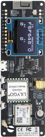
The TTGO T-Beam is a versatile development board designed for IoT (Internet of Things) applications. It combines the power of the ESP32 microcontroller with LoRa (Long Range) communication and GPS functionality, making it ideal for projects requiring low-power, long-range wireless communication and precise location tracking. The T-Beam is widely used in applications such as asset tracking, environmental monitoring, and remote sensing.
Common Applications and Use Cases
- GPS-based asset tracking
- LoRa-based communication networks
- Environmental monitoring systems
- Remote IoT sensor nodes
- Mesh networking for long-range communication
Technical Specifications
The TTGO T-Beam integrates multiple components, each with its own specifications. Below are the key technical details:
General Specifications
| Feature | Specification |
|---|---|
| Microcontroller | ESP32 (dual-core, 240 MHz, Wi-Fi, Bluetooth) |
| LoRa Module | Semtech SX1276 |
| GPS Module | NEO-6M or NEO-M8N (varies by version) |
| Power Supply | 5V via USB-C or 3.7V LiPo battery |
| Battery Connector | JST 2.0mm |
| Charging Circuit | Integrated LiPo charging (via USB-C) |
| Antennas | LoRa and GPS antennas included |
| Dimensions | 54mm x 25mm x 12mm |
Pin Configuration and Descriptions
The TTGO T-Beam has multiple GPIO pins and interfaces. Below is the pinout for the board:
| Pin Name | Pin Number | Description |
|---|---|---|
| 3V3 | - | 3.3V power output for external components |
| GND | - | Ground |
| GPIO21 | 21 | I2C SDA (data line for I2C communication) |
| GPIO22 | 22 | I2C SCL (clock line for I2C communication) |
| GPIO16 | 16 | LoRa Reset |
| GPIO17 | 17 | LoRa DIO1 |
| GPIO18 | 18 | LoRa SCK (SPI clock) |
| GPIO19 | 19 | LoRa MISO (SPI data out) |
| GPIO23 | 23 | LoRa MOSI (SPI data in) |
| GPIO12 | 12 | GPS TX (transmit) |
| GPIO15 | 15 | GPS RX (receive) |
| GPIO4 | 4 | Battery voltage monitoring |
Usage Instructions
How to Use the TTGO T-Beam in a Circuit
Powering the Board:
- Connect the board to a 5V USB-C power source or use a 3.7V LiPo battery.
- Ensure the battery is connected to the JST connector if using battery power.
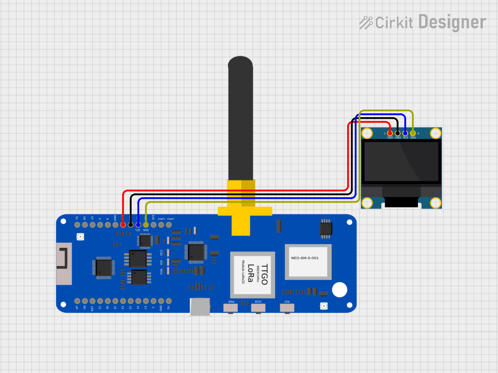
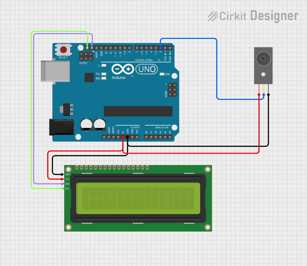
Connecting Peripherals:
- Attach the LoRa and GPS antennas to their respective connectors.
- Use the GPIO pins to connect sensors, actuators, or other peripherals.
Programming the Board:
- Install the Arduino IDE and add the ESP32 board manager URL in the preferences.
- Install the required libraries for LoRa (e.g.,
LoRa.h) and GPS (e.g.,TinyGPS++). - Select the correct board (e.g., "TTGO T-Beam") and port in the Arduino IDE.
Uploading Code:
- Write or load a sketch in the Arduino IDE.
- Connect the T-Beam to your computer via USB-C and upload the code.
Example Code for LoRa and GPS
Below is an example sketch to initialize LoRa and GPS functionality:
#include <LoRa.h>
#include <TinyGPS++.h>
#include <HardwareSerial.h>

// Define LoRa pins
#define LORA_SCK 18  // SPI clock
#define LORA_MISO 19 // SPI MISO
#define LORA_MOSI 23 // SPI MOSI
#define LORA_CS 5    // LoRa chip select
#define LORA_RST 16  // LoRa reset
#define LORA_IRQ 17  // LoRa IRQ

// Define GPS pins
#define GPS_TX 12    // GPS transmit pin
#define GPS_RX 15    // GPS receive pin

// Initialize GPS and LoRa
TinyGPSPlus gps;
HardwareSerial gpsSerial(1);

void setup() {
  // Initialize serial communication
  Serial.begin(115200);
  gpsSerial.begin(9600, SERIAL_8N1, GPS_RX, GPS_TX);

  // Initialize LoRa
  LoRa.setPins(LORA_CS, LORA_RST, LORA_IRQ);
  if (!LoRa.begin(915E6)) { // Set frequency to 915 MHz
    Serial.println("LoRa initialization failed!");
    while (1);
  }
  Serial.println("LoRa initialized successfully.");
}

void loop() {
  // Read GPS data
  while (gpsSerial.available() > 0) {
    gps.encode(gpsSerial.read());
    if (gps.location.isUpdated()) {
      Serial.print("Latitude: ");
      Serial.println(gps.location.lat(), 6);
      Serial.print("Longitude: ");
      Serial.println(gps.location.lng(), 6);
    }
  }

  // Send a LoRa message
  LoRa.beginPacket();
  LoRa.print("Hello from TTGO T-Beam!");
  LoRa.endPacket();

  delay(5000); // Wait 5 seconds before sending the next message
}
Important Considerations and Best Practices
- Always connect the LoRa and GPS antennas before powering the board to avoid damage.
- Use a stable power source to ensure reliable operation.
- Ensure the correct frequency (e.g., 915 MHz or 868 MHz) is set for LoRa based on your region.
- Avoid placing the GPS antenna near sources of interference for accurate location tracking.
Troubleshooting and FAQs
Common Issues and Solutions
LoRa Initialization Fails:
- Ensure the LoRa antenna is connected properly.
- Verify the LoRa frequency matches your region's regulations.
- Check the wiring of the LoRa module if using custom connections.
GPS Not Receiving Data:
- Ensure the GPS antenna is connected and placed in an open area with a clear view of the sky.
- Verify the GPS module's TX and RX pins are correctly connected.
- Allow a few minutes for the GPS module to acquire satellite signals.
Board Not Detected by Arduino IDE:
- Install the correct USB drivers for the ESP32.
- Ensure the correct COM port is selected in the Arduino IDE.
- Try using a different USB cable or port.
FAQs
Can I use the TTGO T-Beam without a battery?
Yes, the board can be powered directly via USB-C.What is the maximum range of LoRa communication?
The range depends on environmental factors but can reach up to 10 km in open areas.How do I monitor battery voltage?
Use GPIO4 to read the battery voltage through an analog-to-digital converter (ADC).
This concludes the documentation for the TTGO T-Beam.
Explore Projects Built with t-beam


Explore Projects Built with t-beam