Cirkit Designer Logo
Cirkit Designer
Your all-in-one circuit design IDE
Home / 
Component Documentation

How to Use usb c charger module: Examples, Pinouts, and Specs

Image of usb c charger module
Cirkit Designer LogoDesign with usb c charger module in Cirkit Designer

Introduction

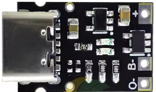
A USB-C charger module is a compact and versatile device designed to provide power to electronic devices through a USB-C connection. It supports fast charging, efficient power delivery, and, in some cases, data transfer capabilities. These modules are widely used in portable electronics, DIY projects, and embedded systems due to their small size and compatibility with modern USB-C standards.

Explore Projects Built with usb c charger module

Use Cirkit Designer to design, explore, and prototype these projects online. Some projects support real-time simulation. Click "Open Project" to start designing instantly!
Battery-Powered 18650 Li-ion Charger with USB Output and Adjustable Voltage Regulator
Image of Breadboard: A project utilizing usb c charger module in a practical application
This circuit is a battery management and power supply system that uses three 3.7V batteries connected to a 3S 10A Li-ion 18650 Charger Protection Board Module for balanced charging and protection. The system includes a TP4056 Battery Charging Protection Module for additional charging safety, a Step Up Boost Power Converter to regulate and boost the voltage, and a USB regulator to provide a stable 5V output, controlled by a push switch.
Cirkit Designer LogoOpen Project in Cirkit Designer
ESP32-Based USB and Battery-Powered Circuit
Image of woot: A project utilizing usb c charger module in a practical application
This circuit features an ESP32 microcontroller powered by a 3.3V regulator, which in turn is powered by a 18650 lithium-ion battery through a charger module. The charger module is designed to charge the battery via a USB connection and also provides power to the regulator. Ground connections are shared among the ESP32, regulator, charger, and USB interfaces, establishing a common reference point for all components.
Cirkit Designer LogoOpen Project in Cirkit Designer
Battery-Powered USB Charger with LED Indicator and DC Motor
Image of Copy of Hand Crank mobile charger : A project utilizing usb c charger module in a practical application
This circuit converts AC power to DC using a bridge rectifier and regulates the voltage to 5V with a 7805 voltage regulator. It powers a USB port and indicates power status with an LED, while also providing a charging interface through a multi-charging cable.
Cirkit Designer LogoOpen Project in Cirkit Designer
Battery-Powered Lora G2 Node Station with 18650 Li-ion Batteries and Boost Converter
Image of Custom-Lora-G2-Node: A project utilizing usb c charger module in a practical application
This circuit is a portable power supply system that uses multiple 18650 Li-ion batteries to provide a stable 5V output through a boost converter. It includes a fast charging module with a USB-C input for recharging the batteries and a battery indicator for monitoring the battery status. The system powers a Lora G2 Node Station, making it suitable for wireless communication applications.
Cirkit Designer LogoOpen Project in Cirkit Designer

Explore Projects Built with usb c charger module

Use Cirkit Designer to design, explore, and prototype these projects online. Some projects support real-time simulation. Click "Open Project" to start designing instantly!
Image of Breadboard: A project utilizing usb c charger module in a practical application
Battery-Powered 18650 Li-ion Charger with USB Output and Adjustable Voltage Regulator
This circuit is a battery management and power supply system that uses three 3.7V batteries connected to a 3S 10A Li-ion 18650 Charger Protection Board Module for balanced charging and protection. The system includes a TP4056 Battery Charging Protection Module for additional charging safety, a Step Up Boost Power Converter to regulate and boost the voltage, and a USB regulator to provide a stable 5V output, controlled by a push switch.
Cirkit Designer LogoOpen Project in Cirkit Designer
Image of woot: A project utilizing usb c charger module in a practical application
ESP32-Based USB and Battery-Powered Circuit
This circuit features an ESP32 microcontroller powered by a 3.3V regulator, which in turn is powered by a 18650 lithium-ion battery through a charger module. The charger module is designed to charge the battery via a USB connection and also provides power to the regulator. Ground connections are shared among the ESP32, regulator, charger, and USB interfaces, establishing a common reference point for all components.
Cirkit Designer LogoOpen Project in Cirkit Designer
Image of Copy of Hand Crank mobile charger : A project utilizing usb c charger module in a practical application
Battery-Powered USB Charger with LED Indicator and DC Motor
This circuit converts AC power to DC using a bridge rectifier and regulates the voltage to 5V with a 7805 voltage regulator. It powers a USB port and indicates power status with an LED, while also providing a charging interface through a multi-charging cable.
Cirkit Designer LogoOpen Project in Cirkit Designer
Image of Custom-Lora-G2-Node: A project utilizing usb c charger module in a practical application
Battery-Powered Lora G2 Node Station with 18650 Li-ion Batteries and Boost Converter
This circuit is a portable power supply system that uses multiple 18650 Li-ion batteries to provide a stable 5V output through a boost converter. It includes a fast charging module with a USB-C input for recharging the batteries and a battery indicator for monitoring the battery status. The system powers a Lora G2 Node Station, making it suitable for wireless communication applications.
Cirkit Designer LogoOpen Project in Cirkit Designer

Common Applications and Use Cases

  • Charging smartphones, tablets, and other USB-C-enabled devices
  • Powering microcontroller-based projects (e.g., Arduino, Raspberry Pi)
  • Integrating into custom power supply designs
  • Providing a reliable power source for wearable devices and IoT applications

Technical Specifications

Below are the typical technical specifications for a USB-C charger module. Note that actual values may vary depending on the specific model.

Parameter Specification
Input Voltage Range 5V to 20V (depending on the module)
Output Voltage 5V, 9V, 12V, 15V, or 20V (PD-supported)
Maximum Output Current 3A (varies by module)
Power Delivery (PD) Supported (up to 60W or higher)
Connector Type USB Type-C
Efficiency Up to 95%
Protection Features Overcurrent, overvoltage, short-circuit
Dimensions Compact (e.g., 25mm x 15mm x 5mm)

Pin Configuration and Descriptions

The USB-C charger module typically has the following pin configuration:

Pin Name Description
VIN Input voltage (connect to power source)
GND Ground connection
VOUT Regulated output voltage (connect to load)
CC1/CC2 Configuration channel pins for USB-C communication
EN Enable pin (optional, used to turn the module on/off)
D+/D- Data lines for USB communication (optional)

Usage Instructions

How to Use the USB-C Charger Module in a Circuit

  1. Connect the Input Voltage:

    • Connect the VIN pin to a suitable power source (e.g., a DC adapter or battery).
    • Ensure the input voltage is within the module's specified range.
  2. Connect the Output Load:

    • Connect the VOUT pin to the device or circuit you want to power.
    • Verify that the load does not exceed the module's maximum current rating.
  3. Enable the Module (if applicable):

    • If the module has an EN (enable) pin, connect it to a HIGH signal to activate the module.
    • Leave the EN pin unconnected or pull it LOW to disable the module.
  4. Optional Connections:

    • For USB-C PD functionality, ensure the CC1 and CC2 pins are properly configured.
    • If data transfer is required, connect the D+ and D- pins to the appropriate data lines.

Important Considerations and Best Practices

  • Heat Dissipation: Ensure proper ventilation or heat sinking if the module operates at high power levels.
  • Input Voltage: Use a stable and clean power source to avoid damaging the module.
  • Load Compatibility: Verify that the connected device supports the output voltage and current provided by the module.
  • USB-C Cable Quality: Use high-quality USB-C cables to ensure reliable power delivery and data transfer.

Example: Using the USB-C Charger Module with an Arduino UNO

The USB-C charger module can be used to power an Arduino UNO. Below is an example circuit and code:
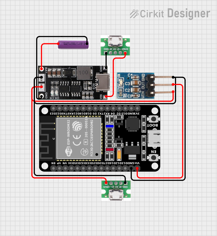
Circuit Connection

  1. Connect the VIN pin of the USB-C charger module to a 9V DC adapter.
  2. Connect the GND pin of the module to the GND pin of the Arduino UNO.
  3. Connect the VOUT pin of the module to the VIN pin of the Arduino UNO.

Example Code

// Example code for Arduino UNO powered by a USB-C charger module
// This code blinks an LED connected to pin 13

void setup() {
  pinMode(13, OUTPUT); // Set pin 13 as an output
}

void loop() {
  digitalWrite(13, HIGH); // Turn the LED on
  delay(1000);            // Wait for 1 second
  digitalWrite(13, LOW);  // Turn the LED off
  delay(1000);            // Wait for 1 second
}

Troubleshooting and FAQs

Common Issues and Solutions

  1. Module Not Powering On:

    • Check the input voltage and ensure it is within the specified range.
    • Verify that the EN pin is connected to a HIGH signal (if applicable).
  2. No Output Voltage:

    • Ensure the load is properly connected to the VOUT pin.
    • Check for any short circuits or overcurrent conditions.
  3. Overheating:

    • Reduce the load current if it exceeds the module's maximum rating.
    • Improve ventilation or add a heat sink to the module.
  4. Inconsistent Output Voltage:

    • Use a stable and clean power source.
    • Check the quality of the USB-C cable and replace it if necessary.

FAQs

Q: Can this module charge a laptop?
A: It depends on the module's power delivery (PD) capabilities. Ensure the module supports the required voltage and current for your laptop.

Q: Is the module compatible with Quick Charge (QC) devices?
A: Some USB-C charger modules support QC standards in addition to PD. Check the module's specifications for compatibility.

Q: Can I use this module for data transfer?
A: Only modules with D+ and D- pins support data transfer. Verify the module's features before use.

Q: How do I know if the module supports fast charging?
A: Look for Power Delivery (PD) or Quick Charge (QC) support in the module's specifications.