How to Use AD5241: Examples, Pinouts, and Specs
Introduction
The AD5241, manufactured by Analog Devices, is a versatile digital potentiometer designed for precision resistance adjustments in electronic circuits. It features a 256-position wiper, enabling fine-tuned control over resistance values. One of its standout features is the inclusion of non-volatile memory, which allows the device to retain its wiper position even after power is removed. This makes it ideal for applications requiring consistent performance and settings retention.
Explore Projects Built with AD5241

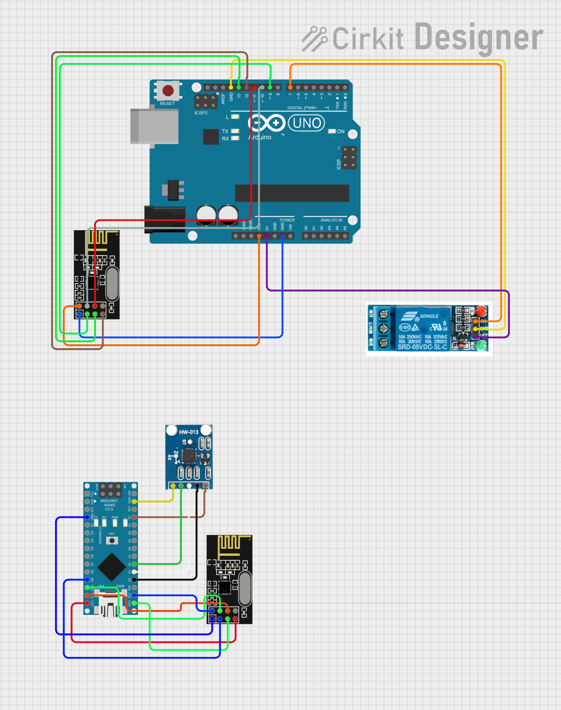

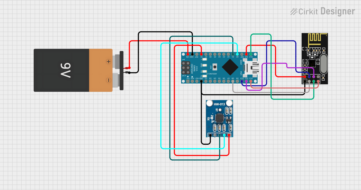
Explore Projects Built with AD5241
Common Applications
- Programmable gain amplifiers
- Offset and bias trimming
- Sensor calibration
- Audio volume control
- Adjustable power supplies
- Data acquisition systems
Technical Specifications
The AD5241 is available in multiple resistance options (10 kΩ, 100 kΩ, and 1 MΩ) and operates over a wide range of supply voltages. Below are the key technical details:
General Specifications
| Parameter | Value |
|---|---|
| Resistance Options | 10 kΩ, 100 kΩ, 1 MΩ |
| Number of Positions | 256 |
| Supply Voltage Range | 2.7 V to 5.5 V |
| Wiper Memory | Non-volatile |
| Interface | I²C |
| Operating Temperature Range | -40°C to +85°C |
| Package Options | 8-lead SOIC, 8-lead TSSOP |
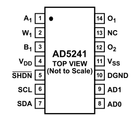
Pin Configuration
The AD5241 is an 8-pin device. Below is the pinout and description:
| Pin No. | Pin Name | Description |
|---|---|---|
| 1 | A | Terminal A of the potentiometer |
| 2 | GND | Ground |
| 3 | SDA | Serial Data Line (I²C interface) |
| 4 | SCL | Serial Clock Line (I²C interface) |
| 5 | WP | Write Protect (active high; prevents changes to the wiper position) |
| 6 | VDD | Positive Supply Voltage |
| 7 | W | Wiper Terminal (adjustable resistance point) |
| 8 | B | Terminal B of the potentiometer |
Usage Instructions
The AD5241 is controlled via an I²C interface, making it easy to integrate into microcontroller-based systems. Below are the steps and considerations for using the component:
Basic Circuit Connection
- Power Supply: Connect the VDD pin to a 2.7 V to 5.5 V power source and the GND pin to ground.
- I²C Interface: Connect the SDA and SCL pins to the corresponding I²C pins on your microcontroller. Use pull-up resistors (typically 4.7 kΩ) on both lines.
- Potentiometer Terminals: Connect terminals A, B, and W as required by your circuit. Terminal W provides the adjustable resistance point.
- Write Protect: If you want to prevent accidental changes to the wiper position, connect the WP pin to VDD. Leave it floating or connect to GND for normal operation.
Example Arduino Code
Below is an example of how to control the AD5241 using an Arduino UNO:
#include <Wire.h> // Include the Wire library for I²C communication

#define AD5241_ADDRESS 0x2C // Default I²C address of the AD5241

void setup() {
  Wire.begin(); // Initialize I²C communication
  Serial.begin(9600); // Initialize serial communication for debugging

  // Set the wiper position to mid-scale (128 out of 256)
  setWiperPosition(128);
}

void loop() {
  // Example: Adjust the wiper position dynamically
  for (int position = 0; position <= 255; position++) {
    setWiperPosition(position);
    delay(100); // Wait 100 ms before the next adjustment
  }
}

// Function to set the wiper position
void setWiperPosition(uint8_t position) {
  Wire.beginTransmission(AD5241_ADDRESS); // Start communication with AD5241
  Wire.write(0x00); // Command byte to set wiper position
  Wire.write(position); // Send the desired wiper position (0-255)
  Wire.endTransmission(); // End communication

  Serial.print("Wiper position set to: ");
  Serial.println(position); // Print the position for debugging
}
Best Practices
- Use decoupling capacitors (e.g., 0.1 µF) near the VDD pin to reduce noise.
- Avoid exceeding the maximum voltage ratings to prevent damage.
- For applications requiring high stability, enable the write-protect feature to lock the wiper position.
Troubleshooting and FAQs
Common Issues
No Response from the Device
- Cause: Incorrect I²C address or wiring.
- Solution: Verify the I²C address (default is 0x2C) and check all connections.
Wiper Position Not Retained After Power Loss
- Cause: Non-volatile memory not updated.
- Solution: Ensure the wiper position is saved to memory before power is removed.
Erratic Behavior
- Cause: Noise on the power supply or I²C lines.
- Solution: Add decoupling capacitors and ensure proper pull-up resistors on SDA and SCL lines.
FAQs
Q: Can the AD5241 be used as a variable resistor?
A: Yes, by connecting the wiper (W) to one of the fixed terminals (A or B), the AD5241 can function as a variable resistor.
Q: How do I reset the wiper to its default position?
A: The wiper resets to the last saved position in non-volatile memory upon power-up. To change this, write a new position to the memory.
Q: What is the maximum current the wiper can handle?
A: The maximum wiper current is 3 mA. Exceeding this limit may damage the device.
Q: Can I use multiple AD5241 devices on the same I²C bus?
A: Yes, you can use up to four devices by configuring their unique I²C addresses using the address pins (if available).
By following this documentation, you can effectively integrate the AD5241 into your projects and achieve precise resistance control.