Cirkit Designer Logo
Cirkit Designer
Your all-in-one circuit design IDE
Home / 
Component Documentation

How to Use KY-018: Examples, Pinouts, and Specs

Image of KY-018
Cirkit Designer LogoDesign with KY-018 in Cirkit Designer

Introduction

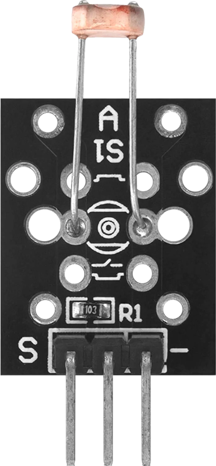
The KY-018 Photoresistor Module by AZ-Delivery is an electronic component that functions as a light sensor. It contains a photoresistor, also known as a light-dependent resistor (LDR), which varies its resistance based on the intensity of light it is exposed to. This characteristic makes the KY-018 suitable for a wide range of applications, such as light level detection, automatic brightness control, and security systems.

Explore Projects Built with KY-018

Use Cirkit Designer to design, explore, and prototype these projects online. Some projects support real-time simulation. Click "Open Project" to start designing instantly!
ESP32-Based Security System with RFID and Laser Tripwire
Image of CPE doorlock system: A project utilizing KY-018 in a practical application
This circuit is designed for a comprehensive security and access control system with motion detection, access via RFID, and a break-beam sensor. It includes a solenoid lock controlled by a relay, visual and audible alerts, and a robust power management system with solar and battery backup to ensure uninterrupted operation.
Cirkit Designer LogoOpen Project in Cirkit Designer
Arduino Nano Joystick-Controlled Bluetooth Module with Battery Power
Image of padelpro transmitter: A project utilizing KY-018 in a practical application
This circuit is a wireless joystick controller that uses an Arduino Nano to read analog signals from a KY-023 Dual Axis Joystick Module and transmits the data via an HC-05 Bluetooth Module. The system is powered by a 18650 Li-Ion battery with a rocker switch for power control.
Cirkit Designer LogoOpen Project in Cirkit Designer
Arduino 101 and KY-023 Joystick Controlled Interface
Image of Joystick: A project utilizing KY-018 in a practical application
This circuit interfaces a KY-023 Dual Axis Joystick Module with an Arduino 101. The joystick's X and Y axis outputs are connected to the analog inputs A0 and A1 of the Arduino, allowing it to read the joystick's position.
Cirkit Designer LogoOpen Project in Cirkit Designer
Wireless Joystick-Controlled Interface with Arduino Nano and NRF24L01
Image of Transmitter 11: A project utilizing KY-018 in a practical application
This circuit features an Arduino Nano interfaced with a KY-023 Dual Axis Joystick Module for analog input, and an NRF24L01 module for wireless communication. The joystick provides x and y-axis control signals to the Arduino's analog inputs and a switch signal to a digital input, while the NRF24L01 enables the Arduino to communicate with other devices wirelessly. The 2x 18650 batteries supply power to the Arduino, which in turn powers the joystick and the NRF24L01 module.
Cirkit Designer LogoOpen Project in Cirkit Designer

Explore Projects Built with KY-018

Use Cirkit Designer to design, explore, and prototype these projects online. Some projects support real-time simulation. Click "Open Project" to start designing instantly!
Image of CPE doorlock system: A project utilizing KY-018 in a practical application
ESP32-Based Security System with RFID and Laser Tripwire
This circuit is designed for a comprehensive security and access control system with motion detection, access via RFID, and a break-beam sensor. It includes a solenoid lock controlled by a relay, visual and audible alerts, and a robust power management system with solar and battery backup to ensure uninterrupted operation.
Cirkit Designer LogoOpen Project in Cirkit Designer
Image of padelpro transmitter: A project utilizing KY-018 in a practical application
Arduino Nano Joystick-Controlled Bluetooth Module with Battery Power
This circuit is a wireless joystick controller that uses an Arduino Nano to read analog signals from a KY-023 Dual Axis Joystick Module and transmits the data via an HC-05 Bluetooth Module. The system is powered by a 18650 Li-Ion battery with a rocker switch for power control.
Cirkit Designer LogoOpen Project in Cirkit Designer
Image of Joystick: A project utilizing KY-018 in a practical application
Arduino 101 and KY-023 Joystick Controlled Interface
This circuit interfaces a KY-023 Dual Axis Joystick Module with an Arduino 101. The joystick's X and Y axis outputs are connected to the analog inputs A0 and A1 of the Arduino, allowing it to read the joystick's position.
Cirkit Designer LogoOpen Project in Cirkit Designer
Image of Transmitter 11: A project utilizing KY-018 in a practical application
Wireless Joystick-Controlled Interface with Arduino Nano and NRF24L01
This circuit features an Arduino Nano interfaced with a KY-023 Dual Axis Joystick Module for analog input, and an NRF24L01 module for wireless communication. The joystick provides x and y-axis control signals to the Arduino's analog inputs and a switch signal to a digital input, while the NRF24L01 enables the Arduino to communicate with other devices wirelessly. The 2x 18650 batteries supply power to the Arduino, which in turn powers the joystick and the NRF24L01 module.
Cirkit Designer LogoOpen Project in Cirkit Designer

Common Applications and Use Cases

  • Automatic lighting control (e.g., street lights that turn on at dusk)
  • Light intensity monitoring for plant growth systems
  • Alarm systems with light-triggered alerts
  • DIY projects involving light sensing, such as a light-activated alarm clock

Technical Specifications

Key Technical Details

  • Operating Voltage: 3.3V to 5V
  • Output Type: Analog voltage corresponding to light intensity
  • Sensitivity: Adjustable via onboard potentiometer
  • Response Time: Typically <20ms
  • Peak Wavelength: ~540nm

Pin Configuration and Descriptions

Pin Number Name Description
1 VCC Power supply (3.3V to 5V)
2 GND Ground
3 A0 Analog output (voltage proportional to light intensity)

Usage Instructions

How to Use the Component in a Circuit

  1. Connect the VCC pin to the power supply (3.3V to 5V).
  2. Connect the GND pin to the ground of the power supply.
  3. Connect the A0 pin to an analog input pin on your microcontroller (e.g., Arduino UNO).

Important Considerations and Best Practices

  • Avoid exposing the photoresistor to extreme light intensities that could damage the sensor.
  • Use a pull-down resistor if you experience floating values when light is absent.
  • Adjust the onboard potentiometer to calibrate the sensitivity of the module to your desired light threshold.

Example Code for Arduino UNO

// KY-018 Photoresistor Module example code for Arduino UNO

int sensorPin = A0; // Select the input pin for the photoresistor
int sensorValue = 0; // Variable to store the value coming from the sensor

void setup() {
  Serial.begin(9600); // Initialize serial communication at 9600 bits per second
}

void loop() {
  sensorValue = analogRead(sensorPin); // Read the value from the sensor
  Serial.println(sensorValue); // Print out the value to the Serial Monitor
  delay(200); // Wait for 200 milliseconds before reading the value again
}

Troubleshooting and FAQs

Common Issues Users Might Face

  • Inconsistent Readings: Ensure that the module is not subjected to intermittent light sources or shadows that could cause fluctuating readings.
  • No Output: Check all connections, especially the VCC and GND, to ensure they are secure. Also, verify that the board is powered correctly.

Solutions and Tips for Troubleshooting

  • If you're getting erratic readings, try adjusting the onboard potentiometer to fine-tune the sensitivity.
  • Ensure that the photoresistor is not directly facing a light source, as this could saturate the sensor and not give accurate readings of ambient light.
  • If the sensor appears unresponsive, measure the voltage across the VCC and GND pins to ensure there is power to the module.

FAQs

Q: Can I connect the KY-018 to a digital input? A: Yes, but you will only get a HIGH or LOW signal depending on the light threshold set by the potentiometer.

Q: What is the range of light intensity the KY-018 can detect? A: The KY-018 can detect a wide range of light intensities, but the exact range depends on the resistance of the LDR and the calibration of the onboard potentiometer.

Q: How do I calibrate the sensitivity of the module? A: Turn the onboard potentiometer clockwise or counterclockwise while monitoring the analog output until you reach the desired sensitivity.

Q: Is the KY-018 waterproof? A: No, the KY-018 is not waterproof and should be protected from moisture to prevent damage.