How to Use traffic light module: Examples, Pinouts, and Specs
Introduction
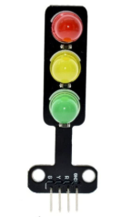
The Traffic Light Module by Arduino is an electronic device designed to simulate the operation of real-world traffic lights. It features three LEDs—red, yellow, and green—arranged in a vertical layout, mimicking the standard traffic light configuration. This module is widely used in educational projects, robotics, model railroads, and traffic control simulations. Its simplicity and versatility make it an excellent tool for learning about basic electronics, programming, and traffic management systems.
Explore Projects Built with traffic light module
Explore Projects Built with traffic light module
Common Applications and Use Cases
- Educational projects to teach programming and electronics.
- Traffic control simulations in robotics and automation.
- Model railroads and dioramas for realistic traffic light effects.
- Prototyping traffic management systems.
- Demonstrating state machines and timing concepts in embedded systems.
Technical Specifications
Key Technical Details
- Operating Voltage: 5V DC
- Current Consumption: ~20mA per LED (typical)
- LED Colors: Red, Yellow, Green
- Control Pins: 3 (one for each LED)
- Dimensions: 30mm x 20mm x 10mm (approx.)
- Connector Type: Male header pins (3-pin or 4-pin configuration)
Pin Configuration and Descriptions
The Traffic Light Module typically has three or four pins, depending on the design. Below is the pin configuration:
| Pin | Label | Description |
|---|---|---|
| 1 | GND | Ground connection (0V) |
| 2 | R | Red LED control pin |
| 3 | Y | Yellow LED control pin |
| 4 | G | Green LED control pin (optional pin) |
Note: Some modules combine the GND pin with the cathodes of all LEDs, while others may have a common anode configuration. Always check the module's datasheet or markings.
Usage Instructions
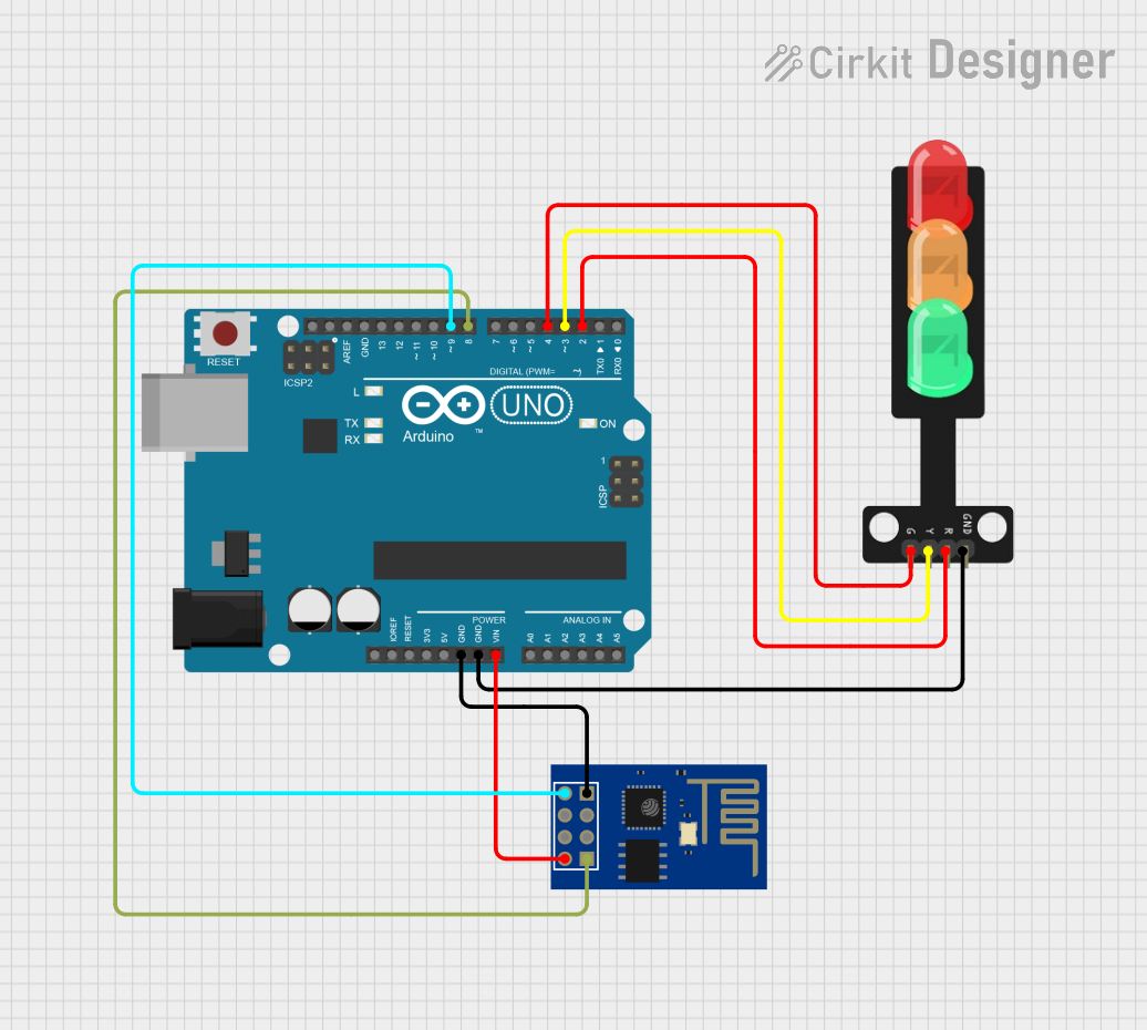
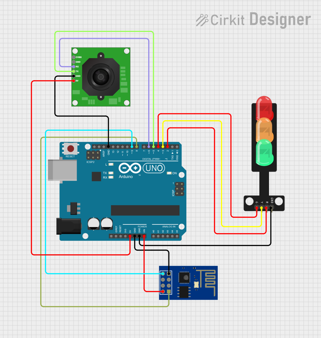
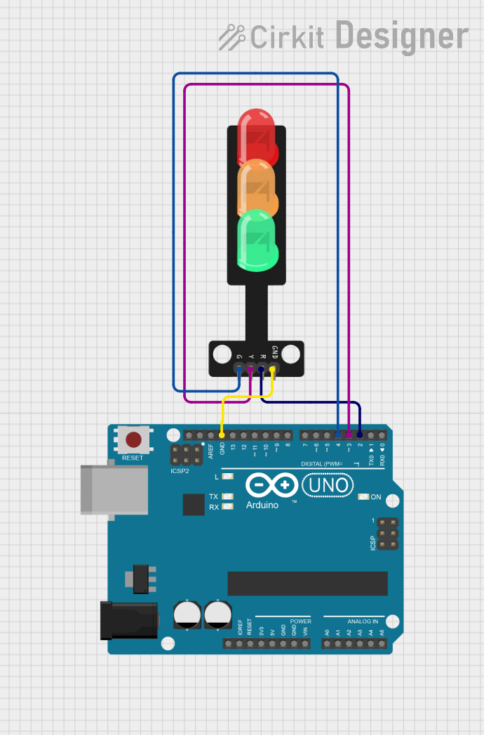
How to Use the Traffic Light Module in a Circuit
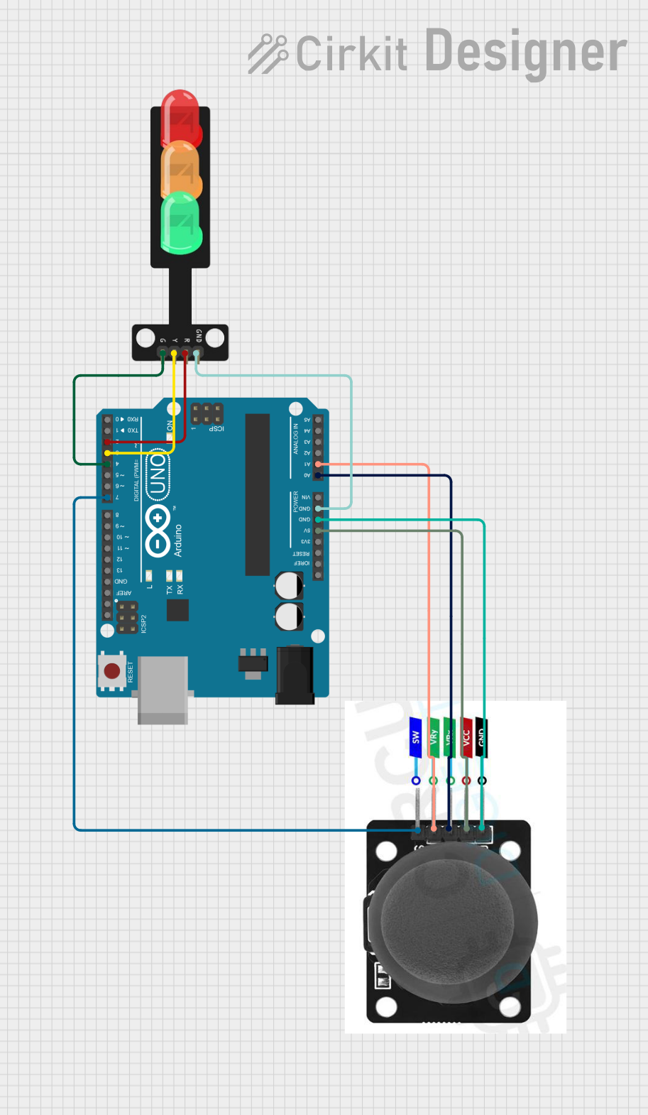
Connect the Module to Power:
- Connect the
GNDpin of the module to the ground (GND) of your power source or microcontroller. - If using a microcontroller like Arduino UNO, connect the control pins (
R,Y,G) to digital output pins.
- Connect the
Write a Control Program:
- Use a microcontroller to control the LEDs by toggling the corresponding pins HIGH or LOW.
- Implement timing delays to simulate real-world traffic light behavior.
Power the Circuit:
- Ensure the module is powered with 5V DC. Avoid exceeding the voltage rating to prevent damage.
Important Considerations and Best Practices
- Resistors: Use current-limiting resistors (220Ω to 330Ω) in series with each LED to prevent overcurrent damage.
- Voltage Levels: Ensure the control pins output 5V logic levels for proper operation.
- Heat Management: Prolonged use of the LEDs at high brightness may generate heat. Allow for adequate ventilation.
- Polarity: Double-check the polarity of connections to avoid damaging the module.
Example Code for Arduino UNO
Below is an example Arduino sketch to control the Traffic Light Module:
// Pin assignments for the Traffic Light Module
const int redPin = 8;    // Red LED connected to digital pin 8
const int yellowPin = 9; // Yellow LED connected to digital pin 9
const int greenPin = 10; // Green LED connected to digital pin 10

void setup() {
  // Set the LED pins as outputs
  pinMode(redPin, OUTPUT);
  pinMode(yellowPin, OUTPUT);
  pinMode(greenPin, OUTPUT);
}

void loop() {
  // Simulate traffic light sequence

  // Turn on the red LED
  digitalWrite(redPin, HIGH);
  delay(5000); // Red light for 5 seconds

  // Turn off the red LED and turn on the yellow LED
  digitalWrite(redPin, LOW);
  digitalWrite(yellowPin, HIGH);
  delay(2000); // Yellow light for 2 seconds

  // Turn off the yellow LED and turn on the green LED
  digitalWrite(yellowPin, LOW);
  digitalWrite(greenPin, HIGH);
  delay(5000); // Green light for 5 seconds

  // Turn off the green LED and repeat the cycle
  digitalWrite(greenPin, LOW);
}
Tip: Adjust the
delay()values in the code to modify the duration of each light.
Troubleshooting and FAQs
Common Issues and Solutions
| Issue | Possible Cause | Solution |
|---|---|---|
| LEDs do not light up | Incorrect wiring or loose connections | Double-check all connections and pin mappings. |
| LEDs are dim or flickering | Insufficient current or missing resistors | Add appropriate current-limiting resistors. |
| Module overheats | Overvoltage or excessive current | Ensure 5V supply and use resistors. |
| Only one LED lights up at a time | Incorrect control logic in the code | Verify the Arduino sketch and pin assignments. |
FAQs
Can I use the Traffic Light Module with a 3.3V microcontroller?
- Yes, but the LEDs may appear dim. Use a level shifter or ensure the LEDs are compatible with 3.3V logic.
Do I need external resistors if my module already has built-in resistors?
- No, if the module includes built-in resistors, additional resistors are unnecessary. Check the module's documentation.
Can I control the module without a microcontroller?
- Yes, you can use switches or a simple timer circuit to control the LEDs manually.
What is the maximum current the module can handle?
- Each LED typically draws ~20mA. Ensure your power source can supply sufficient current for all LEDs.
This documentation provides a comprehensive guide to using the Arduino Traffic Light Module effectively. Whether you're a beginner or an experienced user, this module is a great tool for learning and prototyping traffic control systems.