How to Use Motor switch reverse stop foward: Examples, Pinouts, and Specs
Introduction
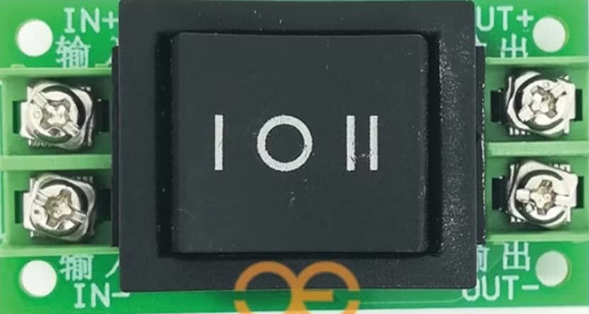
The Motor Switch Reverse Stop Forward (MSRSF) is an electronic component designed to control the direction and operational state of a motor. It is commonly used in applications where motor direction control and the ability to stop the motor are crucial, such as in conveyor systems, automated doors, or robotic arms.
Explore Projects Built with Motor switch reverse stop foward
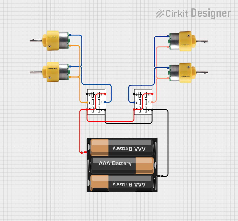

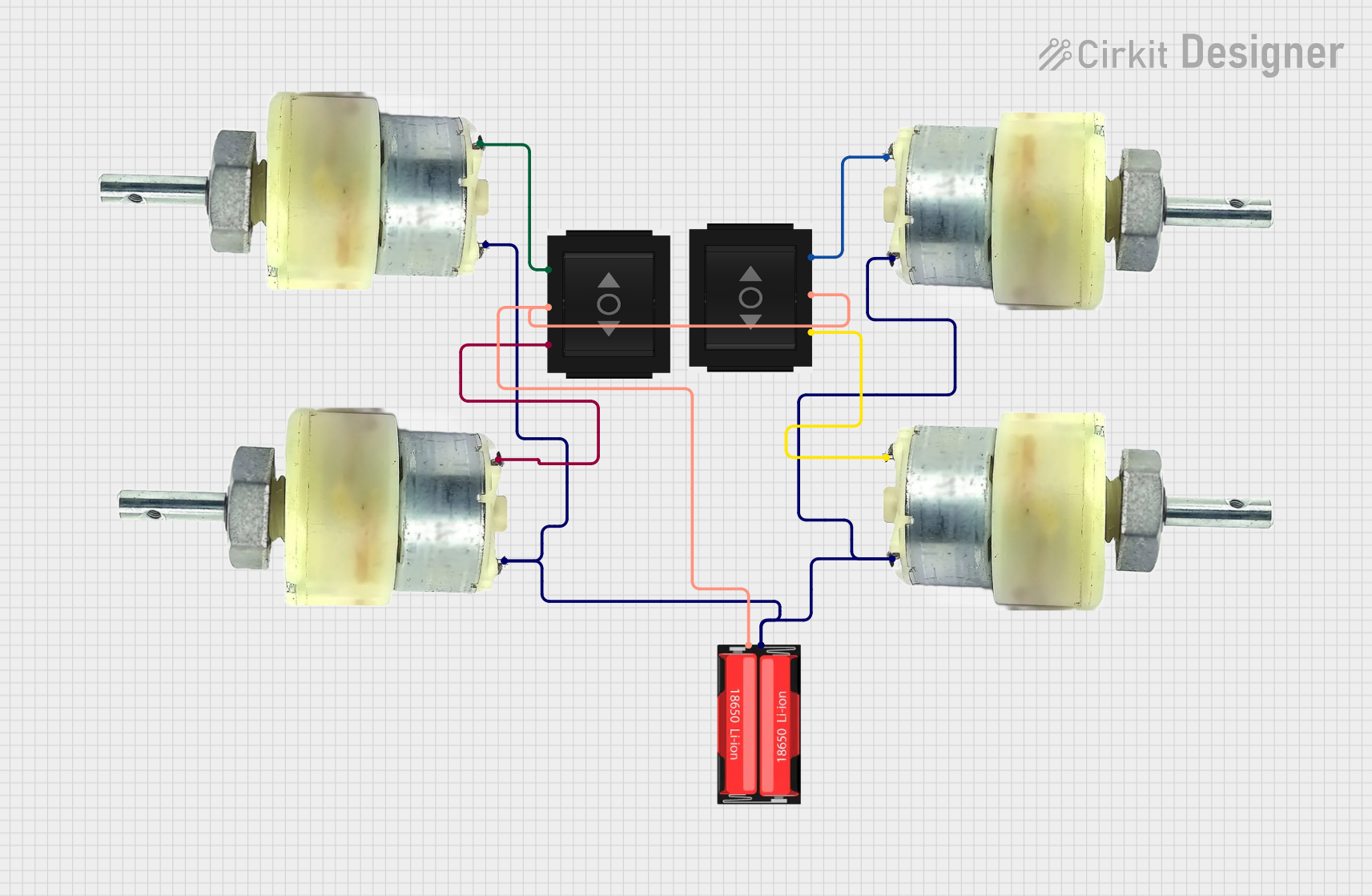
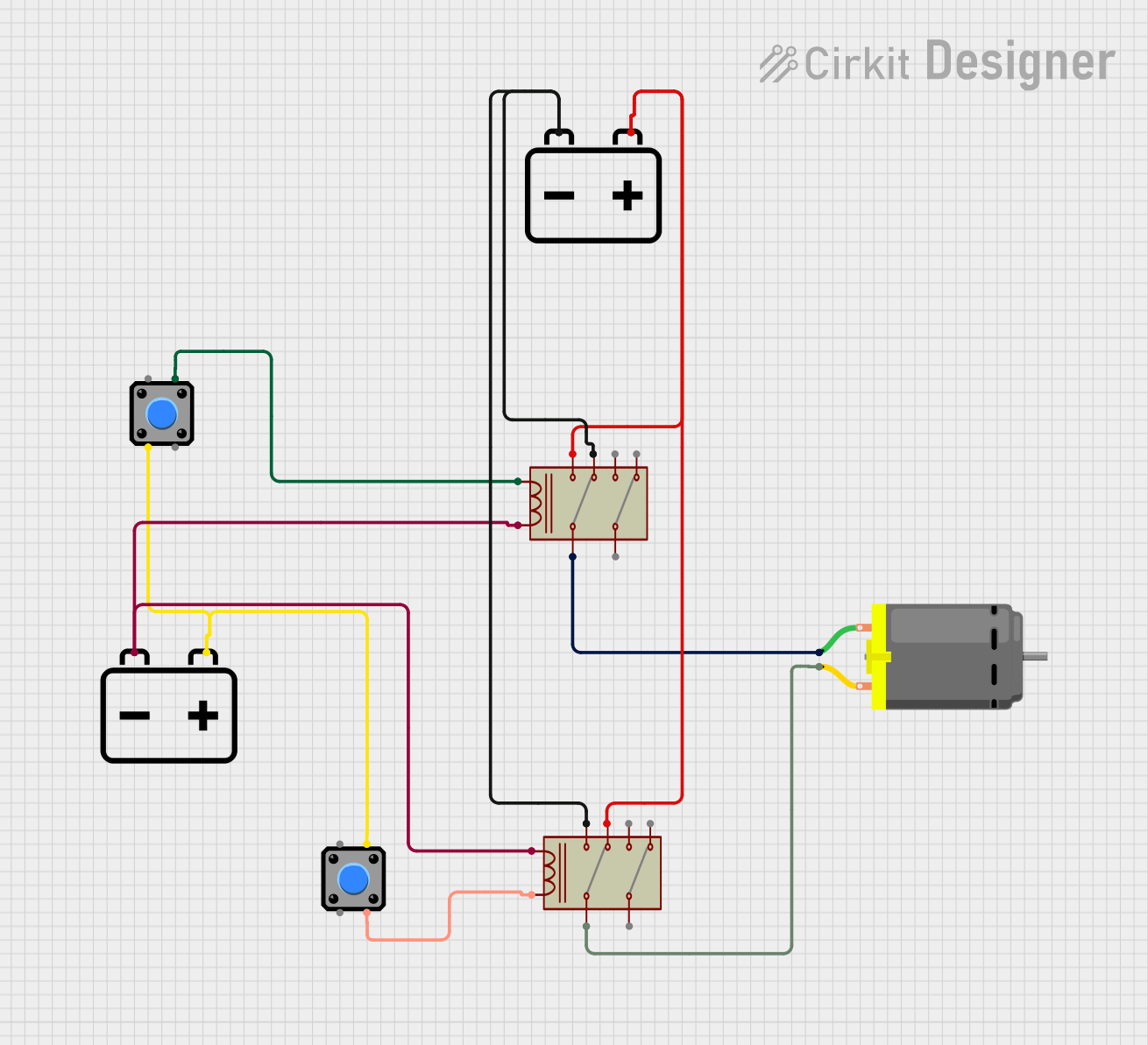
Explore Projects Built with Motor switch reverse stop foward
Common Applications and Use Cases
- Robotics: Direction control for robotic joints.
- Automation: Conveyor belt direction control.
- Vehicle Electronics: Control of electric windows or seats.
- Hobby Projects: RC cars, boats, and drones.
Technical Specifications
Key Technical Details
- Voltage Rating: 3.3V - 5V
- Current Rating: Up to 2A continuous, 5A peak
- Control Logic: TTL compatible
- Operating Temperature: -20°C to 70°C
Pin Configuration and Descriptions
| Pin Number | Name | Description |
|---|---|---|
| 1 | VCC | Power supply (3.3V - 5V) |
| 2 | GND | Ground connection |
| 3 | IN1 | Input control 1 (Forward) |
| 4 | IN2 | Input control 2 (Reverse) |
| 5 | EN | Enable pin (Active High) |
Usage Instructions
How to Use the Component in a Circuit
- Connect the VCC pin to a 3.3V or 5V power supply.
- Connect the GND pin to the common ground in your circuit.
- Connect the IN1 pin to a digital output on your microcontroller to control forward motion.
- Connect the IN2 pin to another digital output to control reverse motion.
- Connect the EN pin to a digital output to enable or disable the motor.
Important Considerations and Best Practices
- Ensure that the power supply can handle the current requirements of the motor.
- Use flyback diodes across the motor terminals to protect against voltage spikes.
- Avoid switching directions without stopping the motor first to prevent damage.
- Implement a software delay between direction changes for safety.
Example Code for Arduino UNO
// Define the control pins
const int forwardPin = 2; // IN1 connected to digital pin 2
const int reversePin = 3; // IN2 connected to digital pin 3
const int enablePin = 4;  // EN connected to digital pin 4

void setup() {
  // Set the control pins as outputs
  pinMode(forwardPin, OUTPUT);
  pinMode(reversePin, OUTPUT);
  pinMode(enablePin, OUTPUT);
}

void loop() {
  // Enable the motor
  digitalWrite(enablePin, HIGH);

  // Move the motor forward
  digitalWrite(forwardPin, HIGH);
  digitalWrite(reversePin, LOW);
  delay(1000); // Run the motor forward for 1 second

  // Stop the motor
  digitalWrite(forwardPin, LOW);
  digitalWrite(reversePin, LOW);
  delay(1000); // Stop the motor for 1 second

  // Move the motor in reverse
  digitalWrite(forwardPin, LOW);
  digitalWrite(reversePin, HIGH);
  delay(1000); // Run the motor in reverse for 1 second

  // Disable the motor
  digitalWrite(enablePin, LOW);
  delay(1000); // Disable the motor for 1 second
}
Troubleshooting and FAQs
Common Issues Users Might Face
- Motor not responding: Check power supply and wiring connections.
- Motor direction not changing: Verify that the control signals to IN1 and IN2 are correct.
- Motor stalling or weak: Ensure the power supply can deliver sufficient current.
Solutions and Tips for Troubleshooting
- Double-check all connections and ensure they are secure.
- Measure the voltage at VCC and GND to confirm the power supply is adequate.
- Use a multimeter to check the continuity of the control signals.
- Implement a "soft start" in your code to gradually increase power to the motor.
FAQs
Q: Can I control the speed of the motor with this switch? A: The MSRSF is primarily for direction control. To control speed, you would need a PWM signal, which is not directly supported by this component.
Q: Is it possible to use this switch with a higher current motor? A: The MSRSF is rated for up to 2A continuous. For higher currents, additional components such as external MOSFETs or relays may be required.
Q: How can I extend the life of my motor when using this switch? A: Avoid rapid direction changes and consider adding a snubber circuit to absorb voltage spikes.
Remember, this documentation is a starting point. Always consult the component's datasheet for the most accurate and detailed information.