Cirkit Designer
Your all-in-one circuit design IDE
Home /
Component Documentation
How to Use QTR 8A: Examples, Pinouts, and Specs
Introduction
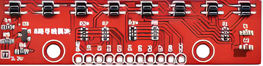
The QTR 8A, manufactured by ROBOLİG(KOKBORU) with part ID kokboru0042 Model, is an array of eight infrared emitter and detector pairs. This component is primarily used for line following and edge detection in robotics. It provides an analog voltage output corresponding to the reflectance of the surface, making it an essential component for autonomous robots and other applications requiring surface reflectance detection.
Explore Projects Built with QTR 8A
Arduino Nano-Powered PID Line Following Robot with Reflectance Sensor Array and Dual Motor Driver
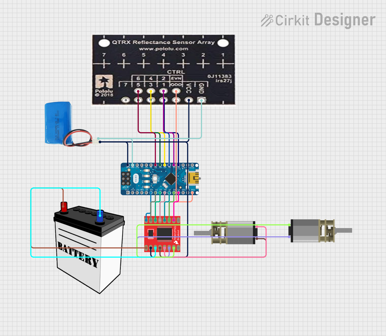
This circuit is designed for an advanced line-following robot that uses a QTRX-HD-07RC Reflectance Sensor Array for line sensing and a Motor Driver 1A Dual TB6612FNG to control two DC Mini Metal Gear Motors. The Arduino Nano serves as the microcontroller, running a PID control algorithm to adjust the motor speeds for precise tracking. Power is supplied by a 5V battery for the logic and a 12V battery for the motor driver.
Adafruit MPU6050 and VL6180X Sensor Interface with Servo Control

This circuit features an Adafruit QT Py microcontroller interfaced with an Adafruit MPU6050 6-axis accelerometer/gyroscope and an Adafruit VL6180X Time of Flight (ToF) distance sensor, both connected via I2C communication. The QT Py also controls a Servomotor SG90, likely for physical actuation based on sensor inputs. The embedded code initializes the sensors, reads their data, and outputs the readings to a serial monitor, with the potential for motion control based on the sensor feedback.
Arduino UNO Based Environmental Monitoring Station with GSM Reporting
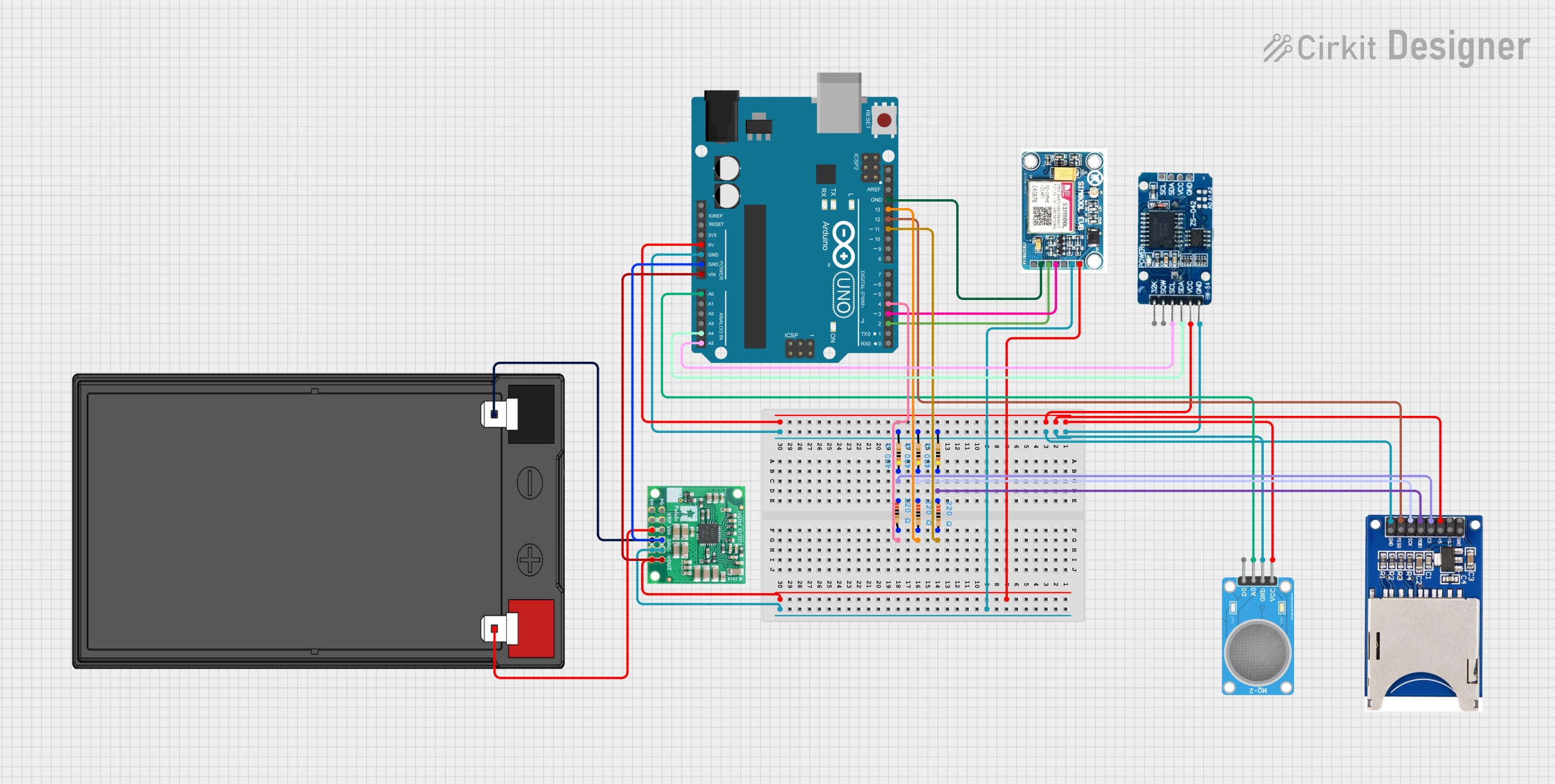
This circuit features an Arduino UNO as the central microcontroller, interfaced with an MQ-2 gas sensor for detecting gases, a DS3231 Real Time Clock for timekeeping, and an SD card reader for data logging. A SIM 800L GSM module is included for cellular communication, and the system is powered by a 12V battery with a 5V step-down voltage regulator to supply the necessary voltage levels. Resistor networks are used for signal conditioning and pull-up/pull-down configurations.
Arduino UNO and A9G GSM/GPRS GPS-Based Air Quality Monitoring System
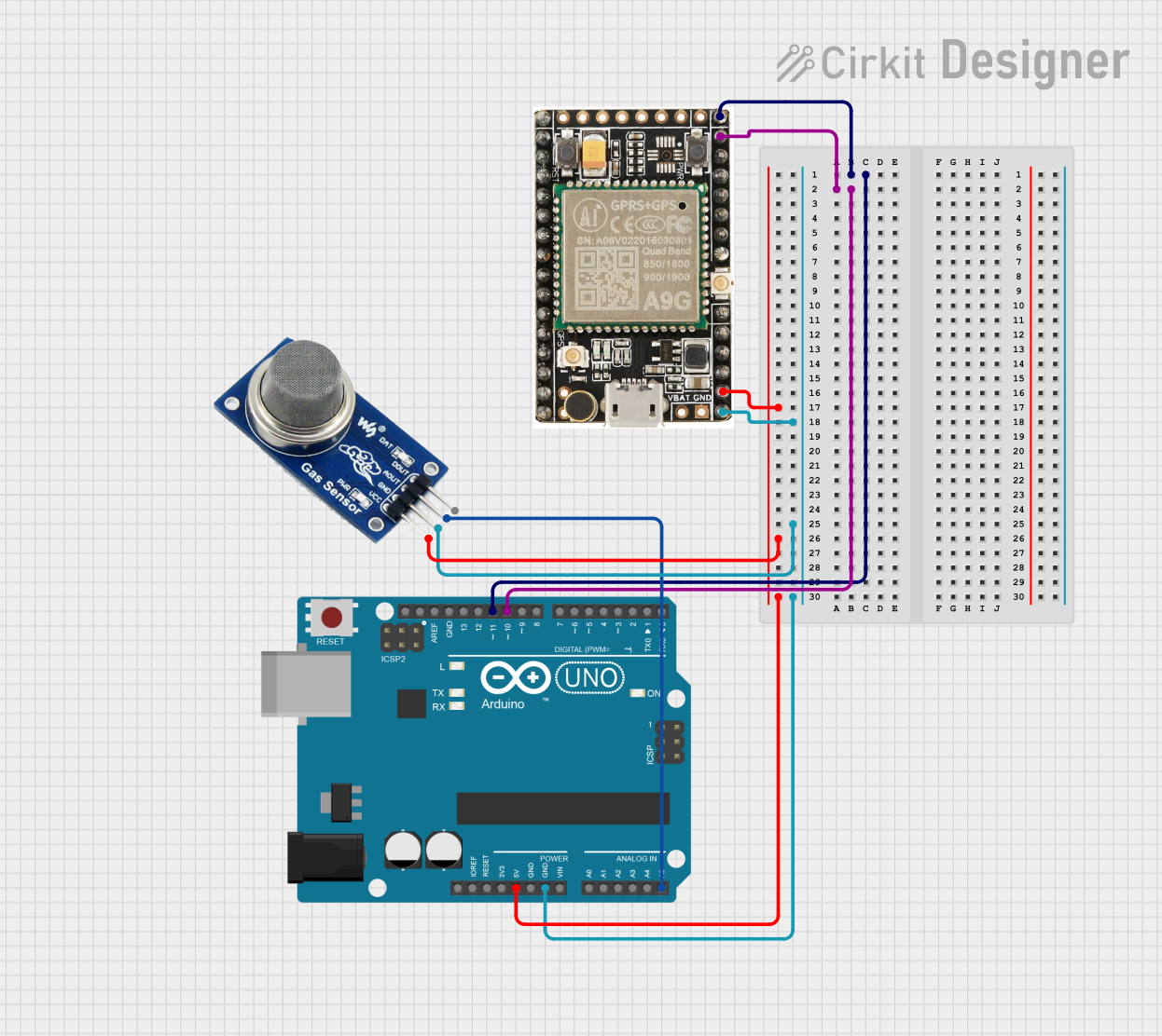
This circuit features an Arduino UNO microcontroller interfaced with an A9G GSM/GPRS+GPS module and an MQ2 gas sensor. The Arduino communicates with the A9G module via digital pins D11 and D10 for data transmission, and it reads analog gas concentration levels from the MQ2 sensor through analog pin A5. Both the A9G module and the MQ2 sensor are powered by the Arduino's 5V output, and all components share a common ground.
Explore Projects Built with QTR 8A
Arduino Nano-Powered PID Line Following Robot with Reflectance Sensor Array and Dual Motor Driver
This circuit is designed for an advanced line-following robot that uses a QTRX-HD-07RC Reflectance Sensor Array for line sensing and a Motor Driver 1A Dual TB6612FNG to control two DC Mini Metal Gear Motors. The Arduino Nano serves as the microcontroller, running a PID control algorithm to adjust the motor speeds for precise tracking. Power is supplied by a 5V battery for the logic and a 12V battery for the motor driver.
Adafruit MPU6050 and VL6180X Sensor Interface with Servo Control
This circuit features an Adafruit QT Py microcontroller interfaced with an Adafruit MPU6050 6-axis accelerometer/gyroscope and an Adafruit VL6180X Time of Flight (ToF) distance sensor, both connected via I2C communication. The QT Py also controls a Servomotor SG90, likely for physical actuation based on sensor inputs. The embedded code initializes the sensors, reads their data, and outputs the readings to a serial monitor, with the potential for motion control based on the sensor feedback.
Arduino UNO Based Environmental Monitoring Station with GSM Reporting
This circuit features an Arduino UNO as the central microcontroller, interfaced with an MQ-2 gas sensor for detecting gases, a DS3231 Real Time Clock for timekeeping, and an SD card reader for data logging. A SIM 800L GSM module is included for cellular communication, and the system is powered by a 12V battery with a 5V step-down voltage regulator to supply the necessary voltage levels. Resistor networks are used for signal conditioning and pull-up/pull-down configurations.
Arduino UNO and A9G GSM/GPRS GPS-Based Air Quality Monitoring System
This circuit features an Arduino UNO microcontroller interfaced with an A9G GSM/GPRS+GPS module and an MQ2 gas sensor. The Arduino communicates with the A9G module via digital pins D11 and D10 for data transmission, and it reads analog gas concentration levels from the MQ2 sensor through analog pin A5. Both the A9G module and the MQ2 sensor are powered by the Arduino's 5V output, and all components share a common ground.
Common Applications and Use Cases
- Line Following Robots: The QTR 8A can be used to detect lines on the ground, allowing robots to follow a predefined path.
- Edge Detection: It can detect edges or boundaries, preventing robots from falling off surfaces.
- Surface Reflectance Measurement: The sensor array can measure the reflectance of different surfaces, useful in various industrial applications.
Technical Specifications
Key Technical Details
| Parameter | Value |
|---|---|
| Operating Voltage | 3.3V to 5V |
| Supply Current | 100 mA (typical) |
| Output Type | Analog |
| Sensor Count | 8 |
| Dimensions | 70 mm x 12 mm x 3 mm |
| Weight | 3 grams |
| Operating Temperature | -10°C to 50°C |
Pin Configuration and Descriptions
| Pin Number | Pin Name | Description |
|---|---|---|
| 1 | VCC | Power supply (3.3V to 5V) |
| 2 | GND | Ground |
| 3 | OUT0 | Analog output from sensor 0 |
| 4 | OUT1 | Analog output from sensor 1 |
| 5 | OUT2 | Analog output from sensor 2 |
| 6 | OUT3 | Analog output from sensor 3 |
| 7 | OUT4 | Analog output from sensor 4 |
| 8 | OUT5 | Analog output from sensor 5 |
| 9 | OUT6 | Analog output from sensor 6 |
| 10 | OUT7 | Analog output from sensor 7 |
| 11 | LEDON | Control pin for turning the IR LEDs on or off |
Usage Instructions
How to Use the Component in a Circuit
- Power Supply: Connect the VCC pin to a 3.3V or 5V power supply and the GND pin to the ground.
- Analog Outputs: Connect the OUT0 to OUT7 pins to the analog input pins of a microcontroller (e.g., Arduino UNO).
- LED Control: Connect the LEDON pin to a digital output pin of the microcontroller to control the IR LEDs.
Important Considerations and Best Practices
- Power Supply: Ensure that the power supply voltage is within the specified range (3.3V to 5V).
- Analog Readings: Use the analogRead() function on the Arduino to read the sensor values.
- LED Control: Use the digitalWrite() function to control the LEDON pin, turning the IR LEDs on or off as needed.
- Calibration: Calibrate the sensors for the specific surface and lighting conditions to improve accuracy.
Sample Arduino Code
// Sample code to read QTR 8A sensor values with Arduino UNO

// Define the analog input pins for the sensors
const int sensorPins[8] = {A0, A1, A2, A3, A4, A5, A6, A7};

// Define the digital output pin for controlling the IR LEDs
const int ledControlPin = 2;

void setup() {
  // Initialize serial communication for debugging
  Serial.begin(9600);

  // Set the LED control pin as an output
  pinMode(ledControlPin, OUTPUT);

  // Turn on the IR LEDs
  digitalWrite(ledControlPin, HIGH);
}

void loop() {
  // Array to store sensor values
  int sensorValues[8];

  // Read the sensor values
  for (int i = 0; i < 8; i++) {
    sensorValues[i] = analogRead(sensorPins[i]);
  }

  // Print the sensor values to the serial monitor
  for (int i = 0; i < 8; i++) {
    Serial.print("Sensor ");
    Serial.print(i);
    Serial.print(": ");
    Serial.print(sensorValues[i]);
    Serial.print("\t");
  }
  Serial.println();

  // Add a small delay before the next reading
  delay(100);
}
Troubleshooting and FAQs
Common Issues Users Might Face
No Output from Sensors:
- Solution: Check the power supply connections and ensure the VCC and GND pins are properly connected.
Inconsistent Readings:
- Solution: Calibrate the sensors for the specific surface and lighting conditions. Ensure the sensors are clean and free from dust.
IR LEDs Not Turning On:
- Solution: Verify the connection to the LEDON pin and ensure it is set to HIGH using the digitalWrite() function.
Solutions and Tips for Troubleshooting
- Check Connections: Ensure all connections are secure and correct.
- Power Supply: Verify that the power supply voltage is within the specified range.
- Sensor Calibration: Calibrate the sensors for the specific environment to improve accuracy.
- Serial Monitor: Use the Serial Monitor in the Arduino IDE to debug and monitor sensor values.
By following this documentation, users can effectively integrate the QTR 8A sensor array into their projects, ensuring accurate line following and edge detection capabilities.