How to Use Fermion Motion Sensor: Examples, Pinouts, and Specs
Introduction
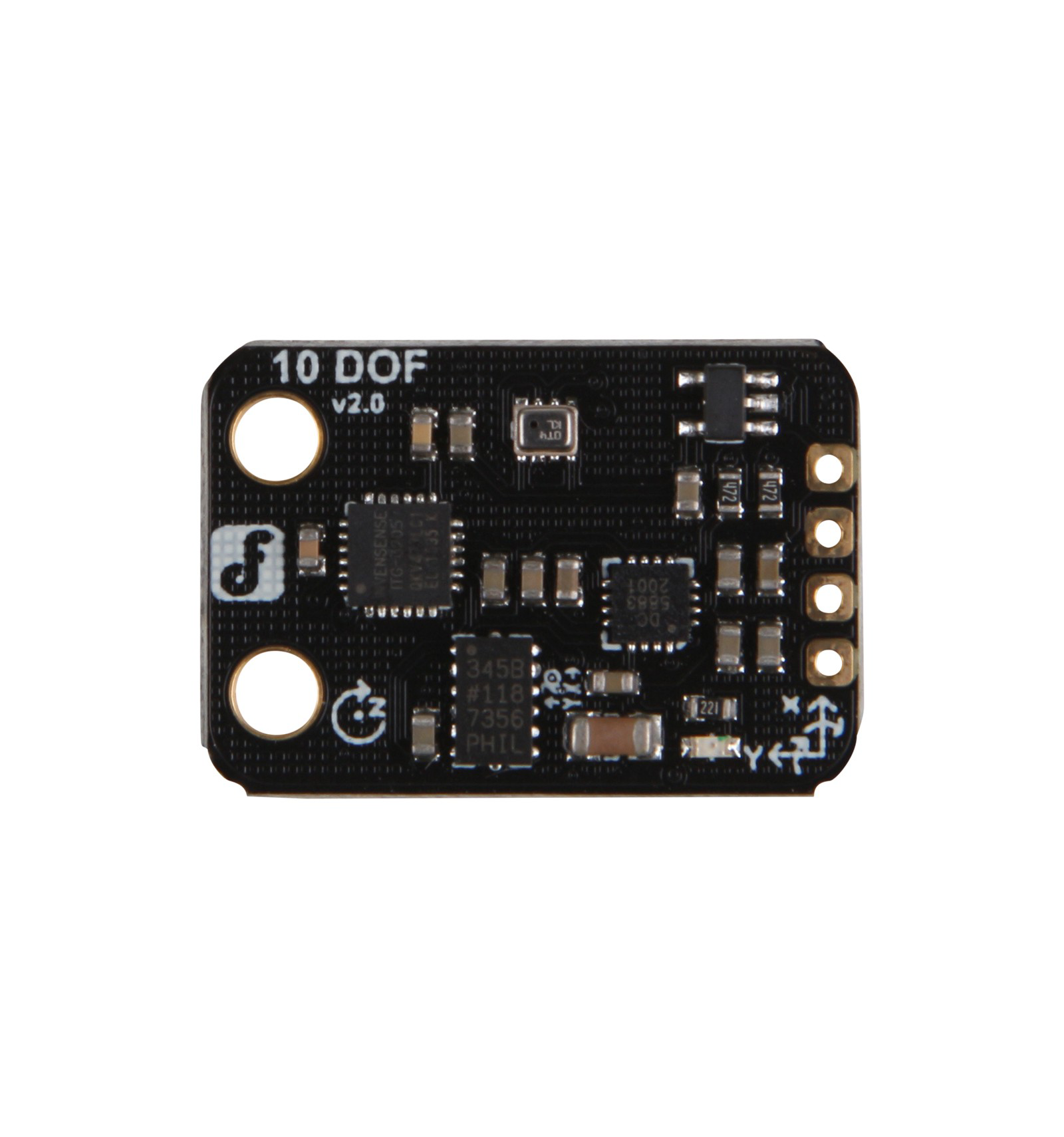
The Fermion Motion Sensor, manufactured by DFRobot (Part ID: 10 DOF), is a highly sensitive device designed to detect motion by measuring changes in the position of fermionic particles. This advanced sensor is ideal for applications requiring precise motion detection, such as security systems, robotics, industrial automation, and smart home devices. Its compact design and high accuracy make it a versatile choice for both hobbyists and professionals.
Explore Projects Built with Fermion Motion Sensor
Explore Projects Built with Fermion Motion Sensor
Technical Specifications
The Fermion Motion Sensor is equipped with advanced sensing technology to ensure reliable performance. Below are the key technical details:
General Specifications
| Parameter | Value |
|---|---|
| Manufacturer | DFRobot |
| Part ID | 10 DOF |
| Operating Voltage | 3.3V - 5V |
| Operating Current | < 10 mA |
| Communication Protocol | I2C, SPI |
| Measurement Range | ±16g (acceleration) |
| Gyroscope Range | ±2000°/s |
| Magnetometer Range | ±8 Gauss |
| Operating Temperature | -40°C to 85°C |
| Dimensions | 20mm x 20mm x 3mm |
Pin Configuration
The Fermion Motion Sensor features a standard pinout for easy integration into circuits. Below is the pin configuration:
| Pin Name | Description |
|---|---|
| VCC | Power supply input (3.3V - 5V) |
| GND | Ground |
| SDA | I2C data line |
| SCL | I2C clock line |
| CS | Chip select for SPI communication |
| MOSI | Master Out Slave In (SPI data input) |
| MISO | Master In Slave Out (SPI data output) |
| SCK | SPI clock line |
| INT | Interrupt pin for motion detection |
Usage Instructions
The Fermion Motion Sensor can be easily integrated into a variety of projects. Below are the steps and best practices for using the sensor:
Connecting the Sensor
- Power Supply: Connect the VCC pin to a 3.3V or 5V power source and the GND pin to ground.
- Communication Interface:
- For I2C: Connect the SDA and SCL pins to the corresponding pins on your microcontroller.
- For SPI: Connect the CS, MOSI, MISO, and SCK pins to the respective SPI pins on your microcontroller.
- Interrupt Pin: Optionally, connect the INT pin to a digital input pin on your microcontroller to handle motion detection interrupts.
Example Code for Arduino UNO
Below is an example of how to use the Fermion Motion Sensor with an Arduino UNO via the I2C interface:
#include <Wire.h>

// Define the I2C address of the Fermion Motion Sensor
#define SENSOR_ADDR 0x68

void setup() {
  Wire.begin(); // Initialize I2C communication
  Serial.begin(9600); // Start serial communication for debugging

  // Initialize the sensor
  Wire.beginTransmission(SENSOR_ADDR);
  Wire.write(0x6B); // Access the power management register
  Wire.write(0x00); // Wake up the sensor
  Wire.endTransmission();

  Serial.println("Fermion Motion Sensor Initialized");
}

void loop() {
  Wire.beginTransmission(SENSOR_ADDR);
  Wire.write(0x3B); // Start reading acceleration data
  Wire.endTransmission(false);
  Wire.requestFrom(SENSOR_ADDR, 6); // Request 6 bytes of data

  if (Wire.available() == 6) {
    int16_t accelX = (Wire.read() << 8) | Wire.read();
    int16_t accelY = (Wire.read() << 8) | Wire.read();
    int16_t accelZ = (Wire.read() << 8) | Wire.read();

    // Print acceleration data to the serial monitor
    Serial.print("Accel X: ");
    Serial.print(accelX);
    Serial.print(" | Accel Y: ");
    Serial.print(accelY);
    Serial.print(" | Accel Z: ");
    Serial.println(accelZ);
  }

  delay(500); // Wait for 500ms before the next reading
}
Best Practices
- Use pull-up resistors (4.7kΩ recommended) on the SDA and SCL lines for I2C communication.
- Ensure proper grounding to avoid noise interference.
- Avoid placing the sensor near strong magnetic fields or vibrations, as these can affect accuracy.
- Calibrate the sensor for your specific application to achieve optimal performance.
Troubleshooting and FAQs
Common Issues and Solutions
No Data from the Sensor:
- Ensure the sensor is powered correctly (check VCC and GND connections).
- Verify the I2C or SPI connections and ensure the correct address or chip select pin is used.
- Check for loose or faulty wiring.
Inaccurate Readings:
- Calibrate the sensor using appropriate software or libraries.
- Avoid placing the sensor near sources of electromagnetic interference.
Interrupt Pin Not Working:
- Ensure the INT pin is connected to a digital input pin on the microcontroller.
- Verify that the interrupt functionality is enabled in the sensor's configuration.
FAQs
Q: Can the Fermion Motion Sensor be used with 3.3V microcontrollers?
A: Yes, the sensor supports both 3.3V and 5V logic levels, making it compatible with a wide range of microcontrollers.
Q: How do I switch between I2C and SPI communication?
A: The communication mode is determined by the connections. For I2C, connect SDA and SCL. For SPI, connect CS, MOSI, MISO, and SCK.
Q: Is the sensor suitable for outdoor use?
A: The sensor can operate in a wide temperature range (-40°C to 85°C), but it is not waterproof. Use appropriate enclosures for outdoor applications.
By following this documentation, you can effectively integrate and utilize the Fermion Motion Sensor in your projects.