How to Use TS5823 : Examples, Pinouts, and Specs

 Design with TS5823 in Cirkit Designer
Introduction
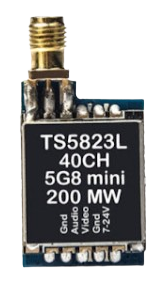
The TS5823 is a high-performance, low-noise operational amplifier (op-amp) specifically designed for audio applications. It offers a wide bandwidth, low total harmonic distortion (THD), and a high slew rate, making it ideal for high-fidelity audio signal processing. The TS5823 is commonly used in audio preamplifiers, equalizers, active filters, and other audio-related circuits where precision and low noise are critical.
Explore Projects Built with TS5823

 Open Project in Cirkit Designer
 Open Project in Cirkit Designer
 Open Project in Cirkit Designer
 Open Project in Cirkit Designer
Explore Projects Built with TS5823

 Open Project in Cirkit Designer
 Open Project in Cirkit Designer
 Open Project in Cirkit Designer
 Open Project in Cirkit Designer
Common Applications:
- Audio preamplifiers and mixers
- Equalizers and tone control circuits
- Active filters and oscillators
- Signal conditioning in audio systems
- High-fidelity audio equipment
Technical Specifications
The TS5823 is designed to deliver exceptional performance in demanding audio applications. Below are its key technical specifications:
| Parameter | Value |
|---|---|
| Supply Voltage Range | ±5V to ±15V |
| Input Offset Voltage | ≤ 1 mV |
| Input Bias Current | ≤ 50 nA |
| Gain Bandwidth Product | 10 MHz |
| Slew Rate | 20 V/µs |
| Total Harmonic Distortion | ≤ 0.001% |
| Input Impedance | 10 MΩ |
| Output Impedance | ≤ 100 Ω |
| Operating Temperature Range | -40°C to +85°C |
| Package Type | DIP-8, SOIC-8 |
Pin Configuration and Descriptions
The TS5823 is typically available in an 8-pin DIP or SOIC package. Below is the pinout and description:
| Pin Number | Pin Name | Description |
|---|---|---|
| 1 | Offset Null | Used for offset voltage adjustment (optional) |
| 2 | Inverting Input (-) | Inverting input terminal for the op-amp |
| 3 | Non-Inverting Input (+) | Non-inverting input terminal for the op-amp |
| 4 | V- (Negative Supply) | Negative power supply terminal |
| 5 | Offset Null | Used for offset voltage adjustment (optional) |
| 6 | Output | Output terminal of the op-amp |
| 7 | V+ (Positive Supply) | Positive power supply terminal |
| 8 | NC (No Connection) | Not connected internally |
Usage Instructions
The TS5823 is straightforward to use in audio and general-purpose circuits. Below are the steps and considerations for integrating it into your design:
Basic Circuit Configuration
- Power Supply: Connect the TS5823 to a dual power supply (e.g., ±12V) for optimal performance. Ensure proper decoupling capacitors (e.g., 0.1 µF ceramic and 10 µF electrolytic) are placed close to the power supply pins to minimize noise.
- Input Connections: Connect the audio signal to the non-inverting or inverting input, depending on the desired configuration (e.g., non-inverting amplifier or inverting amplifier).
- Feedback Network: Use resistors and capacitors in the feedback loop to set the gain and frequency response of the amplifier.
- Output Load: Ensure the load impedance is within the recommended range (≥ 2 kΩ) to avoid distortion or instability.
Example Circuit: Non-Inverting Amplifier
Below is an example of a non-inverting amplifier circuit using the TS5823:
        +V (e.g., +12V)
         |
         |
        .-.
        | | 10 µF
        | |
        '-'
         |
         +-------------------+
         |                   |
         |                   |
Input ---+---[R1]---+        |
                  (|+)       |
                   |         |
                   |         |
                  (|-)---[R2]--- GND
                   |
                   |
                  Output
Arduino Integration
While the TS5823 is not directly programmable, it can be used in conjunction with an Arduino UNO for audio signal processing. For example, you can use the TS5823 to amplify an audio signal before feeding it into the Arduino's analog input for analysis or processing.
Example Arduino Code
// Example: Reading an amplified audio signal using Arduino UNO
// Ensure the TS5823 is configured as a preamplifier for the audio signal.

const int audioInputPin = A0; // Analog pin connected to TS5823 output

void setup() {
  Serial.begin(9600); // Initialize serial communication
}

void loop() {
  int audioSignal = analogRead(audioInputPin);
  // Read the amplified audio signal (0-1023 range for 10-bit ADC)

  Serial.println(audioSignal);
  // Print the signal value to the Serial Monitor for analysis

  delay(10); // Small delay to avoid overwhelming the serial output
}
Best Practices
- Use shielded cables for audio input and output connections to minimize noise and interference.
- Place decoupling capacitors close to the power supply pins to ensure stable operation.
- Avoid overloading the output by ensuring the load impedance is within the recommended range.
- For high-precision applications, consider adjusting the offset voltage using the offset null pins.
Troubleshooting and FAQs
Common Issues and Solutions
Distorted Output Signal:
- Cause: Overloading the output or insufficient power supply decoupling.
- Solution: Ensure the load impedance is ≥ 2 kΩ and add decoupling capacitors near the power supply pins.
High Noise Levels:
- Cause: Poor grounding or unshielded cables.
- Solution: Use a proper grounding scheme and shielded cables for audio connections.
No Output Signal:
- Cause: Incorrect pin connections or power supply issues.
- Solution: Double-check the pin connections and ensure the power supply is within the specified range.
Offset Voltage Drift:
- Cause: Temperature variations or improper offset adjustment.
- Solution: Use the offset null pins to fine-tune the offset voltage.
FAQs
Q1: Can the TS5823 be used with a single power supply?
A1: Yes, the TS5823 can operate with a single supply (e.g., 0V to +12V), but the input signal must be biased appropriately to stay within the op-amp's input range.
Q2: What is the maximum gain I can achieve with the TS5823?
A2: The maximum gain depends on the feedback network and the op-amp's bandwidth. For audio applications, gains up to 100 (40 dB) are common while maintaining low distortion.
Q3: Is the TS5823 suitable for high-frequency applications?
A3: The TS5823 has a gain bandwidth product of 10 MHz, making it suitable for audio and low RF applications, but it may not be ideal for very high-frequency circuits.
Q4: Can I use the TS5823 for DC signal amplification?
A4: Yes, the TS5823 can amplify DC signals, but ensure proper offset adjustment to minimize drift.