How to Use 15 pin "D-sub": Examples, Pinouts, and Specs
Introduction
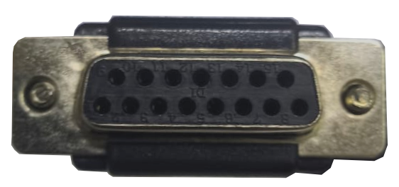
The 15-pin D-sub connector, also known as a D-subminiature connector, is a versatile and widely used interface for serial communication. It features a D-shaped metal shell that provides mechanical stability and ensures proper orientation during connection. This connector is commonly used in applications such as connecting computers to peripherals like monitors (e.g., VGA connections), printers, and other devices requiring reliable data transmission.
Explore Projects Built with 15 pin "D-sub"


Explore Projects Built with 15 pin "D-sub"
Common Applications and Use Cases
- VGA (Video Graphics Array) connections for monitors and projectors
- Serial communication in industrial equipment
- Gaming controllers and legacy hardware interfaces
- Test and measurement equipment
- Audio and video signal transmission
Technical Specifications
Key Technical Details
- Number of Pins: 15
- Connector Type: D-subminiature (D-shaped shell)
- Shell Material: Metal (provides EMI shielding)
- Pin Spacing: 2.77 mm (0.109 inches)
- Current Rating: Typically 5A per pin (varies by manufacturer)
- Voltage Rating: Up to 300V (varies by manufacturer)
- Mounting Style: Through-hole or panel mount
- Gender: Male (plug) or Female (socket)
- Durability: Rated for 200-500 mating cycles (varies by manufacturer)
Pin Configuration and Descriptions
The 15-pin D-sub connector is most commonly associated with VGA connections. Below is the pinout for a standard VGA application:
| Pin Number | Signal Name | Description |
|---|---|---|
| 1 | Red | Red video signal |
| 2 | Green | Green video signal |
| 3 | Blue | Blue video signal |
| 4 | ID2/Reserved | Monitor identification or reserved |
| 5 | Ground | Ground |
| 6 | Red Ground | Ground for red video signal |
| 7 | Green Ground | Ground for green video signal |
| 8 | Blue Ground | Ground for blue video signal |
| 9 | +5V | +5V DC power supply |
| 10 | Ground | Ground |
| 11 | ID0/Reserved | Monitor identification or reserved |
| 12 | ID1/SDA | Monitor identification or I2C data line |
| 13 | Horizontal Sync | Horizontal synchronization signal |
| 14 | Vertical Sync | Vertical synchronization signal |
| 15 | ID3/SCL | Monitor identification or I2C clock line |
Note: Pin assignments may vary for non-VGA applications. Always refer to the specific datasheet for your use case.
Usage Instructions
How to Use the Component in a Circuit
- Identify the Application: Determine the purpose of the 15-pin D-sub connector in your project (e.g., VGA, serial communication).
- Select the Correct Gender: Use a male connector for the cable and a female connector for the device or panel mount.
- Soldering: For through-hole connectors, solder the pins to a PCB. Ensure proper alignment and avoid solder bridges.
- Cable Assembly: If using a cable-mounted connector, crimp or solder the wires to the appropriate pins based on the pinout.
- Mounting: Secure the connector to a panel or enclosure using screws and nuts to ensure mechanical stability.
- Testing: Verify continuity and proper signal transmission using a multimeter or oscilloscope.
Important Considerations and Best Practices
- EMI Shielding: Ensure the metal shell is properly grounded to reduce electromagnetic interference.
- Cable Strain Relief: Use strain relief mechanisms to prevent damage to the wires or solder joints.
- Pinout Verification: Double-check the pinout for your specific application to avoid miswiring.
- Connector Durability: Avoid excessive force during mating and unmating to extend the lifespan of the connector.
Example: Connecting a VGA Monitor to an Arduino UNO
While the Arduino UNO does not natively support VGA output, you can use a VGA adapter circuit to generate video signals. Below is an example of how to generate a simple VGA signal using an Arduino:
// Simple VGA signal generator for Arduino UNO
// Generates a basic pattern on a VGA monitor
// Connect pins as follows:
// - Pin 9: Horizontal Sync (VGA Pin 13)
// - Pin 10: Vertical Sync (VGA Pin 14)
// - Pin 11: Red Signal (VGA Pin 1)
// - Pin 12: Green Signal (VGA Pin 2)
// - Pin 13: Blue Signal (VGA Pin 3)

const int hSyncPin = 9;  // Horizontal sync pin
const int vSyncPin = 10; // Vertical sync pin
const int redPin = 11;   // Red signal pin
const int greenPin = 12; // Green signal pin
const int bluePin = 13;  // Blue signal pin

void setup() {
  pinMode(hSyncPin, OUTPUT);
  pinMode(vSyncPin, OUTPUT);
  pinMode(redPin, OUTPUT);
  pinMode(greenPin, OUTPUT);
  pinMode(bluePin, OUTPUT);
}

void loop() {
  // Generate a simple VGA signal
  digitalWrite(hSyncPin, LOW);  // Horizontal sync pulse
  delayMicroseconds(5);         // Sync pulse duration
  digitalWrite(hSyncPin, HIGH);

  digitalWrite(vSyncPin, LOW);  // Vertical sync pulse
  delayMicroseconds(5);         // Sync pulse duration
  digitalWrite(vSyncPin, HIGH);

  // Generate a color pattern
  digitalWrite(redPin, HIGH);   // Turn on red
  digitalWrite(greenPin, LOW);  // Turn off green
  digitalWrite(bluePin, LOW);   // Turn off blue
  delay(100);                   // Hold the color for 100ms

  digitalWrite(redPin, LOW);    // Turn off red
  digitalWrite(greenPin, HIGH); // Turn on green
  digitalWrite(bluePin, LOW);   // Turn off blue
  delay(100);                   // Hold the color for 100ms

  digitalWrite(redPin, LOW);    // Turn off red
  digitalWrite(greenPin, LOW);  // Turn off green
  digitalWrite(bluePin, HIGH);  // Turn on blue
  delay(100);                   // Hold the color for 100ms
}
Note: This is a basic example and may not produce a stable VGA signal. For advanced VGA projects, consider using dedicated VGA libraries or hardware.
Troubleshooting and FAQs
Common Issues and Solutions
No Signal on the Monitor
- Cause: Incorrect pin connections or loose cables.
- Solution: Verify the pinout and ensure all connections are secure.
Flickering or Distorted Display
- Cause: Poor grounding or interference.
- Solution: Ensure the metal shell is grounded and use shielded cables.
Connector Damage
- Cause: Excessive force during mating/unmating.
- Solution: Handle the connector gently and avoid misalignment.
Signal Loss
- Cause: Long cable runs or poor-quality cables.
- Solution: Use shorter, high-quality cables with proper shielding.
FAQs
Q: Can I use the 15-pin D-sub connector for non-VGA applications?
- A: Yes, the 15-pin D-sub connector can be used for various serial communication and custom applications. Ensure the pinout matches your requirements.
Q: How do I clean a dirty or corroded connector?
- A: Use a soft brush and isopropyl alcohol to clean the pins. Avoid abrasive materials that may damage the connector.
Q: Is the 15-pin D-sub connector still relevant in modern devices?
- A: While newer interfaces like HDMI and USB are more common, the 15-pin D-sub connector remains widely used in legacy systems and industrial applications.
For additional support, consult the datasheet or contact the manufacturer of your specific connector.