How to Use LM393: Examples, Pinouts, and Specs
Introduction
The LM393 is a dual comparator integrated circuit (IC) designed to compare two input voltages and output a digital signal based on the comparison. It features two independent voltage comparators in a single package, making it versatile and efficient for a wide range of applications. The LM393 operates with a wide supply voltage range and is known for its low power consumption.
Explore Projects Built with LM393
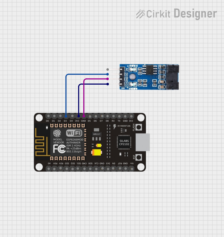
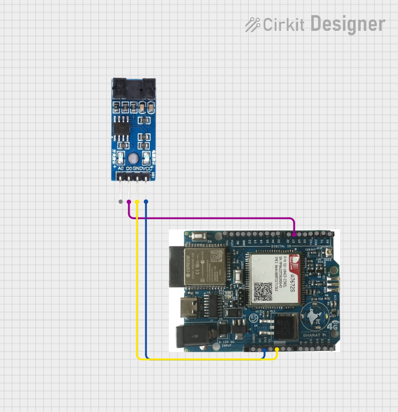


Explore Projects Built with LM393
Common Applications
- Voltage level detection
- Signal conditioning
- Zero-crossing detectors
- Pulse-width modulation (PWM) circuits
- Analog-to-digital signal conversion
- Control systems and automation
Technical Specifications
The LM393 is a robust and reliable IC with the following key technical specifications:
| Parameter | Value |
|---|---|
| Supply Voltage (Vcc) | 2V to 36V |
| Input Offset Voltage | ±5mV (typical) |
| Input Common-Mode Voltage | 0V to Vcc - 1.5V |
| Output Voltage (Low State) | 0.2V (typical) at 4mA |
| Output Sink Current | 16mA (maximum) |
| Response Time | 1.3µs (typical) |
| Operating Temperature | -40°C to +85°C |
| Package Types | DIP-8, SOIC-8, TSSOP-8 |
Pin Configuration and Descriptions
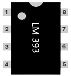
The LM393 is typically available in an 8-pin package. Below is the pinout and description:
| Pin Number | Pin Name | Description |
|---|---|---|
| 1 | Output 1 | Output of comparator 1 |
| 2 | Inverting Input 1 | Inverting input of comparator 1 |
| 3 | Non-Inverting Input 1 | Non-inverting input of comparator 1 |
| 4 | GND | Ground (0V reference) |
| 5 | Non-Inverting Input 2 | Non-inverting input of comparator 2 |
| 6 | Inverting Input 2 | Inverting input of comparator 2 |
| 7 | Output 2 | Output of comparator 2 |
| 8 | Vcc | Positive power supply |
Usage Instructions
The LM393 is straightforward to use in a circuit. Below are the steps and considerations for its proper usage:
How to Use the LM393 in a Circuit
- Power Supply: Connect the Vcc pin (Pin 8) to a positive voltage source (2V to 36V) and the GND pin (Pin 4) to ground.
- Input Connections:
- Connect the voltage to be compared to the non-inverting (Pin 3 or Pin 5) and inverting (Pin 2 or Pin 6) inputs.
- Ensure the input voltage levels are within the common-mode voltage range (0V to Vcc - 1.5V).
- Output: The output (Pin 1 or Pin 7) will be in a low state (close to 0V) if the inverting input voltage is higher than the non-inverting input voltage. Otherwise, the output will be in a high-impedance state (requires a pull-up resistor to Vcc).
- Pull-Up Resistor: Use a pull-up resistor (e.g., 10kΩ) on the output pin to ensure proper logic levels.
Example: Connecting LM393 to an Arduino UNO
The LM393 can be used with an Arduino UNO for voltage level detection. Below is an example circuit and code:
Circuit Description
- Connect the LM393's Vcc to the Arduino's 5V pin and GND to the Arduino's GND.
- Connect the non-inverting input (Pin 3) to the voltage to be monitored.
- Connect the inverting input (Pin 2) to a reference voltage (e.g., from a voltage divider).
- Connect the output (Pin 1) to a digital input pin on the Arduino (e.g., Pin 2).
Arduino Code
// LM393 Comparator Example with Arduino UNO
// This code reads the output of the LM393 and turns on an LED if the monitored
// voltage exceeds the reference voltage.

const int lm393OutputPin = 2; // LM393 output connected to digital pin 2
const int ledPin = 13;        // Onboard LED pin

void setup() {
  pinMode(lm393OutputPin, INPUT); // Set LM393 output pin as input
  pinMode(ledPin, OUTPUT);        // Set LED pin as output
  Serial.begin(9600);             // Initialize serial communication
}

void loop() {
  int comparatorState = digitalRead(lm393OutputPin); // Read LM393 output

  if (comparatorState == HIGH) {
    digitalWrite(ledPin, HIGH); // Turn on LED if voltage exceeds reference
    Serial.println("Voltage is above reference level.");
  } else {
    digitalWrite(ledPin, LOW);  // Turn off LED otherwise
    Serial.println("Voltage is below reference level.");
  }

  delay(500); // Wait for 500ms before next reading
}
Important Considerations and Best Practices
- Input Voltage Range: Ensure the input voltages are within the specified common-mode range to avoid incorrect operation.
- Pull-Up Resistor: Always use a pull-up resistor on the output pin to achieve proper logic levels.
- Decoupling Capacitor: Place a decoupling capacitor (e.g., 0.1µF) near the Vcc pin to reduce noise and improve stability.
- Output Current: Do not exceed the maximum output sink current (16mA) to prevent damage to the IC.
Troubleshooting and FAQs
Common Issues and Solutions
No Output Signal:
- Check the power supply connections (Vcc and GND).
- Verify that the input voltages are within the common-mode range.
- Ensure a pull-up resistor is connected to the output pin.
Incorrect Output Behavior:
- Confirm that the inverting and non-inverting inputs are connected correctly.
- Check for noise or instability in the input signals and add filtering if necessary.
Overheating:
- Ensure the output current does not exceed the maximum rating (16mA).
- Verify that the supply voltage is within the specified range.
FAQs
Q: Can the LM393 be used for high-speed applications?
A: The LM393 has a typical response time of 1.3µs, making it suitable for moderate-speed applications but not ideal for high-speed requirements.
Q: What happens if the input voltage exceeds the common-mode range?
A: The comparator may not function correctly, and the output could become unpredictable. Always ensure the input voltages are within the specified range.
Q: Can the LM393 output directly drive an LED?
A: Yes, but ensure the current through the LED does not exceed the maximum output sink current (16mA). Use a current-limiting resistor in series with the LED.
By following this documentation, users can effectively integrate the LM393 into their projects and troubleshoot common issues with ease.