Cirkit Designer Logo
Cirkit Designer
Your all-in-one circuit design IDE
Home / 
Component Documentation

How to Use dot Matrix Single: Examples, Pinouts, and Specs

Image of dot Matrix Single
Cirkit Designer LogoDesign with dot Matrix Single in Cirkit Designer

Introduction

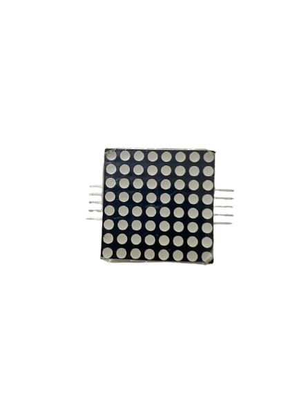
A dot matrix single is a display device that consists of a grid of LEDs or other light-emitting elements arranged in a matrix format. It allows for the representation of characters, symbols, or images by illuminating specific dots in the matrix. These displays are widely used in applications such as digital clocks, scrolling text displays, scoreboards, and simple graphic displays. Their compact size, versatility, and ease of use make them a popular choice for both hobbyist and professional projects.

Explore Projects Built with dot Matrix Single

Use Cirkit Designer to design, explore, and prototype these projects online. Some projects support real-time simulation. Click "Open Project" to start designing instantly!
Arduino UNO Real-Time Clock and Dot Matrix Display System
Image of jam: A project utilizing dot Matrix Single in a practical application
This circuit consists of an Arduino UNO microcontroller connected to an RTC DS3231 module for real-time clock functionality and an 8x32 dot matrix display for visual output. The Arduino communicates with the RTC module via I2C protocol and controls the dot matrix display using SPI protocol.
Cirkit Designer LogoOpen Project in Cirkit Designer
Arduino UNO Controlled LED Matrix Display with Interactive Pushbuttons
Image of Cykel: A project utilizing dot Matrix Single in a practical application
This circuit features an Arduino UNO microcontroller connected to multiple 8x8 LED matrix displays and pushbuttons. The pushbuttons are interfaced with digital pins D2, D3, and D4 on the Arduino for input, while the LED matrices are connected to digital pins D5 through D10 for control signals. Additionally, there is a single red LED with a series resistor connected to pin D12, likely used as an indicator light.
Cirkit Designer LogoOpen Project in Cirkit Designer
ESP32-Controlled Dual 8x8 LED Matrix Display with NTP Time Synchronization
Image of time: A project utilizing dot Matrix Single in a practical application
This circuit features an ESP32 microcontroller connected to two cascaded 8x8 LED matrix displays, powered by a 3.3V battery. The ESP32 drives the displays to show time and other information, with the code indicating functionality for connecting to WiFi, synchronizing time via NTP, and displaying data on the matrices using custom fonts. Additionally, there is a separate 3.3V battery powering a red LED, which appears to function as a simple indicator light.
Cirkit Designer LogoOpen Project in Cirkit Designer
Arduino UNO Controlled LED Matrix and LCD Interface with Joystick Interaction
Image of Digital Game Circuit: A project utilizing dot Matrix Single in a practical application
This circuit features an Arduino UNO microcontroller interfaced with an 8x8 LED matrix, an LCD screen, and a KY-023 Dual Axis Joystick Module. The Arduino controls the LED matrix via digital pins D10-D12 and powers the matrix, LCD, and joystick module from its 5V output. The joystick's analog outputs are connected to the Arduino's analog inputs A0 and A1 for position sensing, while the LCD is controlled through digital pins D2-D6 and D13 for display purposes.
Cirkit Designer LogoOpen Project in Cirkit Designer

Explore Projects Built with dot Matrix Single

Use Cirkit Designer to design, explore, and prototype these projects online. Some projects support real-time simulation. Click "Open Project" to start designing instantly!
Image of jam: A project utilizing dot Matrix Single in a practical application
Arduino UNO Real-Time Clock and Dot Matrix Display System
This circuit consists of an Arduino UNO microcontroller connected to an RTC DS3231 module for real-time clock functionality and an 8x32 dot matrix display for visual output. The Arduino communicates with the RTC module via I2C protocol and controls the dot matrix display using SPI protocol.
Cirkit Designer LogoOpen Project in Cirkit Designer
Image of Cykel: A project utilizing dot Matrix Single in a practical application
Arduino UNO Controlled LED Matrix Display with Interactive Pushbuttons
This circuit features an Arduino UNO microcontroller connected to multiple 8x8 LED matrix displays and pushbuttons. The pushbuttons are interfaced with digital pins D2, D3, and D4 on the Arduino for input, while the LED matrices are connected to digital pins D5 through D10 for control signals. Additionally, there is a single red LED with a series resistor connected to pin D12, likely used as an indicator light.
Cirkit Designer LogoOpen Project in Cirkit Designer
Image of time: A project utilizing dot Matrix Single in a practical application
ESP32-Controlled Dual 8x8 LED Matrix Display with NTP Time Synchronization
This circuit features an ESP32 microcontroller connected to two cascaded 8x8 LED matrix displays, powered by a 3.3V battery. The ESP32 drives the displays to show time and other information, with the code indicating functionality for connecting to WiFi, synchronizing time via NTP, and displaying data on the matrices using custom fonts. Additionally, there is a separate 3.3V battery powering a red LED, which appears to function as a simple indicator light.
Cirkit Designer LogoOpen Project in Cirkit Designer
Image of Digital Game Circuit: A project utilizing dot Matrix Single in a practical application
Arduino UNO Controlled LED Matrix and LCD Interface with Joystick Interaction
This circuit features an Arduino UNO microcontroller interfaced with an 8x8 LED matrix, an LCD screen, and a KY-023 Dual Axis Joystick Module. The Arduino controls the LED matrix via digital pins D10-D12 and powers the matrix, LCD, and joystick module from its 5V output. The joystick's analog outputs are connected to the Arduino's analog inputs A0 and A1 for position sensing, while the LCD is controlled through digital pins D2-D6 and D13 for display purposes.
Cirkit Designer LogoOpen Project in Cirkit Designer

Technical Specifications

Below are the key technical details and pin configuration for a standard dot matrix single display:

Key Technical Details

  • Matrix Size: Typically 8x8 (64 LEDs)
  • Operating Voltage: 3.3V to 5V
  • Current per LED: ~10-20mA (depending on brightness)
  • Power Consumption: Varies based on the number of LEDs lit
  • Control Method: Multiplexing (row and column addressing)
  • Dimensions: Commonly 32mm x 32mm for an 8x8 matrix
  • LED Color: Red (common), Green, Blue, or RGB (depending on the model)

Pin Configuration and Descriptions

The dot matrix single display typically has 16 pins for an 8x8 matrix, with 8 pins for rows and 8 pins for columns. Below is a table describing the pin configuration:

Pin Number Label Description
1 R1 Row 1 control
2 R2 Row 2 control
3 R3 Row 3 control
4 R4 Row 4 control
5 R5 Row 5 control
6 R6 Row 6 control
7 R7 Row 7 control
8 R8 Row 8 control
9 C1 Column 1 control
10 C2 Column 2 control
11 C3 Column 3 control
12 C4 Column 4 control
13 C5 Column 5 control
14 C6 Column 6 control
15 C7 Column 7 control
16 C8 Column 8 control

Note: The exact pin configuration may vary depending on the manufacturer. Always refer to the datasheet for your specific dot matrix model.

Usage Instructions

How to Use the Component in a Circuit
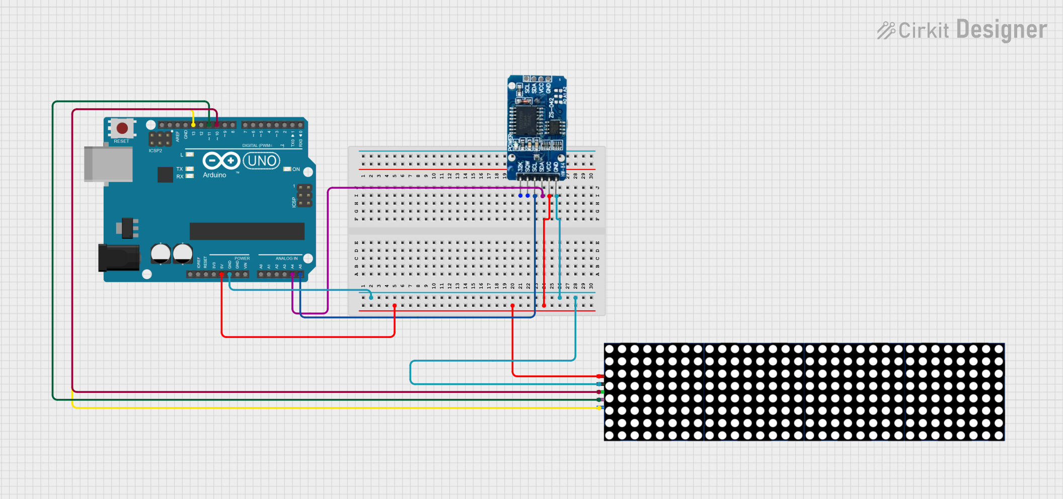
  1. Connect the Pins:
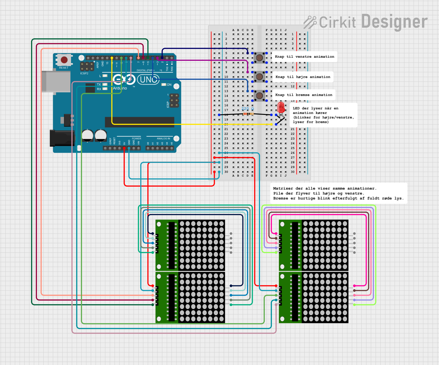
    • Connect the row pins (R1-R8) and column pins (C1-C8) to a microcontroller or driver IC (e.g., MAX7219).
    • Use current-limiting resistors if necessary to protect the LEDs.
  2. Multiplexing:
    • The dot matrix operates using a multiplexing technique, where rows and columns are activated in sequence to light up specific LEDs.
    • A driver IC like the MAX7219 can simplify this process by handling the multiplexing internally.
  3. Power Supply:
    • Ensure the power supply matches the operating voltage of the dot matrix (typically 5V).
    • Avoid exceeding the current rating to prevent damage to the LEDs.

Important Considerations and Best Practices

  • Brightness Control: Use pulse-width modulation (PWM) to adjust the brightness of the LEDs.
  • Driver IC: For ease of use, consider using a driver IC like the MAX7219, which reduces the number of pins required for control.
  • Heat Management: Avoid lighting up too many LEDs simultaneously to prevent overheating.
  • Testing: Test the connections with a simple program to ensure all LEDs are functional before integrating the display into a larger project.

Example Code for Arduino UNO

Below is an example of how to control a dot matrix single display using an Arduino UNO and the MAX7219 driver IC:

#include <LedControl.h> // Include the LedControl library for MAX7219

// Initialize the LedControl object
// Parameters: DIN pin, CLK pin, CS pin, number of displays
LedControl lc = LedControl(12, 11, 10, 1);

void setup() {
  lc.shutdown(0, false); // Wake up the MAX7219
  lc.setIntensity(0, 8); // Set brightness level (0-15)
  lc.clearDisplay(0);    // Clear the display
}

void loop() {
  // Display a simple pattern (e.g., a smiley face)
  byte smiley[8] = {
    B00111100, // Row 1
    B01000010, // Row 2
    B10100101, // Row 3
    B10000001, // Row 4
    B10100101, // Row 5
    B10011001, // Row 6
    B01000010, // Row 7
    B00111100  // Row 8
  };

  for (int row = 0; row < 8; row++) {
    lc.setRow(0, row, smiley[row]); // Set each row of the display
  }

  delay(1000); // Wait for 1 second
  lc.clearDisplay(0); // Clear the display
  delay(1000); // Wait for 1 second
}

Note: Ensure the MAX7219 is correctly wired to the Arduino UNO and the dot matrix display. The LedControl library simplifies communication with the MAX7219.

Troubleshooting and FAQs

Common Issues Users Might Face

  1. No LEDs Lighting Up:
    • Check the power supply and ensure the voltage matches the display's requirements.
    • Verify all connections, especially the row and column pins.
  2. Dim or Flickering LEDs:
    • Ensure the current-limiting resistors are correctly sized.
    • Check for loose connections or insufficient power supply.
  3. Incorrect Patterns Displayed:
    • Verify the row and column pin mappings in your code.
    • Ensure the driver IC (if used) is functioning correctly.

Solutions and Tips for Troubleshooting

  • Test Individual LEDs: Use a multimeter or a simple circuit to test individual LEDs in the matrix.
  • Use a Known Working Code: Start with a basic example code to verify the hardware setup.
  • Check the Datasheet: Refer to the datasheet for your specific dot matrix model to confirm pin configurations and electrical characteristics.

By following this documentation, you should be able to successfully integrate and use a dot matrix single display in your projects.