How to Use D-SUB DE15 (DB15) cable connector: Examples, Pinouts, and Specs
Introduction
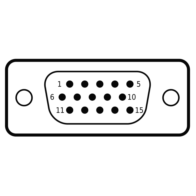
The D-SUB DE15 (commonly referred to as DB15) cable connector is a widely used electrical connector designed for video and data transmission. It features 15 pins arranged in three rows within a D-shaped metal shell, which provides mechanical stability and shielding against electromagnetic interference (EMI).
This connector is most commonly associated with VGA (Video Graphics Array) connections, where it is used to link computer graphics cards to monitors. It is also employed in other applications, such as industrial equipment, projectors, and KVM (Keyboard, Video, Mouse) switches.
Explore Projects Built with D-SUB DE15 (DB15) cable connector


Explore Projects Built with D-SUB DE15 (DB15) cable connector
Common Applications:
- VGA connections for computer monitors and projectors
- Analog video signal transmission
- Industrial control systems
- KVM switches for managing multiple computers
- Legacy gaming and audio equipment
Technical Specifications
Key Technical Details:
- Connector Type: D-SUB DE15 (DB15)
- Number of Pins: 15 (arranged in 3 rows of 5 pins each)
- Shell Material: Metal (typically nickel-plated for durability and EMI shielding)
- Contact Material: Gold-plated or tin-plated for reliable conductivity
- Voltage Rating: Typically up to 300V
- Current Rating: 3A per pin (varies by manufacturer)
- Operating Temperature Range: -55°C to +105°C
- Mounting Style: Through-hole or panel mount
- Cable Type: Shielded VGA cable (commonly 15-conductor)
Pin Configuration and Descriptions:
The D-SUB DE15 connector pinout is standardized for VGA applications. Below is the pin configuration:
| Pin Number | Signal Name | Description |
|---|---|---|
| 1 | Red | Red video signal |
| 2 | Green | Green video signal |
| 3 | Blue | Blue video signal |
| 4 | ID2/Reserved | Monitor identification or reserved |
| 5 | Ground | Ground |
| 6 | Red Ground | Ground for red video signal |
| 7 | Green Ground | Ground for green video signal |
| 8 | Blue Ground | Ground for blue video signal |
| 9 | +5V | +5V DC power supply (optional) |
| 10 | Ground | Ground |
| 11 | ID0/Reserved | Monitor identification or reserved |
| 12 | ID1/SDA | Monitor identification or I2C data line |
| 13 | Horizontal Sync (HS) | Horizontal synchronization signal |
| 14 | Vertical Sync (VS) | Vertical synchronization signal |
| 15 | ID3/SCL | Monitor identification or I2C clock line |
Usage Instructions
How to Use the D-SUB DE15 Connector in a Circuit:
- Identify the Pinout: Refer to the pin configuration table above to understand the function of each pin.
- Soldering the Connector:
- If using a panel-mount connector, solder the wires to the appropriate pins.
- Ensure proper grounding by connecting all ground pins (5, 6, 7, 8, and 10) to the circuit ground.
- Cable Shielding:
- Use a shielded VGA cable to minimize interference.
- Connect the cable shield to the metal shell of the connector for additional EMI protection.
- Testing the Connection:
- Use a multimeter to verify continuity between the pins and the connected device.
- Ensure there are no short circuits between adjacent pins.
Important Considerations:
- Signal Quality: For high-resolution video signals, use high-quality cables with proper shielding to avoid signal degradation.
- Cable Length: Keep the cable length as short as possible to reduce signal loss and interference.
- Compatibility: Ensure the connected devices support VGA or the specific application for which the DE15 connector is being used.
Example: Connecting to an Arduino UNO
While the D-SUB DE15 connector is not directly compatible with Arduino UNO for VGA signal generation, it can be used in conjunction with a VGA signal generator circuit. Below is an example of Arduino code to generate a basic VGA signal:
// Simple VGA signal generator for Arduino UNO
// Generates a basic horizontal and vertical sync signal
// Note: This is a basic example and does not produce a full VGA image.

const int hSyncPin = 9; // Horizontal sync signal pin
const int vSyncPin = 10; // Vertical sync signal pin

void setup() {
  pinMode(hSyncPin, OUTPUT);
  pinMode(vSyncPin, OUTPUT);
}

void loop() {
  // Generate horizontal sync pulse
  digitalWrite(hSyncPin, LOW);
  delayMicroseconds(4); // Horizontal sync pulse width (approx. 4 µs)
  digitalWrite(hSyncPin, HIGH);
  delayMicroseconds(31); // Horizontal back porch (approx. 31 µs)

  // Generate vertical sync pulse
  static int lineCount = 0;
  lineCount++;
  if (lineCount >= 525) { // Total lines in a VGA frame
    digitalWrite(vSyncPin, LOW);
    delayMicroseconds(64); // Vertical sync pulse width (approx. 64 µs)
    digitalWrite(vSyncPin, HIGH);
    lineCount = 0;
  }
}
Notes:
- This code generates only the sync signals required for VGA. Additional circuitry is needed to generate RGB video signals.
- Use resistors and capacitors as needed to match the VGA signal specifications.
Troubleshooting and FAQs
Common Issues:
No Signal on Monitor:
- Cause: Incorrect pin connections or loose cable.
- Solution: Double-check the pinout and ensure all connections are secure.
Poor Video Quality:
- Cause: Low-quality or excessively long cable.
- Solution: Use a high-quality shielded VGA cable and minimize cable length.
Interference or Flickering:
- Cause: Insufficient grounding or EMI.
- Solution: Ensure all ground pins are properly connected and the cable shield is grounded.
Overheating Connector:
- Cause: Excessive current through the pins.
- Solution: Verify the current rating of the connector and reduce the load if necessary.
FAQs:
Q: Can the D-SUB DE15 connector be used for digital signals?
A: The DE15 connector is primarily designed for analog VGA signals. However, it can be repurposed for digital signals in custom applications, provided the voltage and current ratings are not exceeded.Q: What is the maximum resolution supported by a VGA connection?
A: VGA connections using the DE15 connector can support resolutions up to 2048x1536 at 60Hz, depending on the cable quality and signal source.Q: How do I clean the connector?
A: Use a soft brush or compressed air to remove dust. Avoid using liquids that may damage the metal contacts.
This concludes the documentation for the D-SUB DE15 (DB15) cable connector.