How to Use ESP32 DEVKIT V1: Examples, Pinouts, and Specs
Introduction
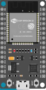
The ESP32 DEVKIT V1 is a versatile development board built around the ESP32 chip, which integrates Wi-Fi and Bluetooth capabilities. This board is widely used in Internet of Things (IoT) applications, home automation, robotics, and other projects requiring wireless communication. Its compact design, powerful processing capabilities, and extensive GPIO options make it an excellent choice for both beginners and experienced developers.
Explore Projects Built with ESP32 DEVKIT V1


Explore Projects Built with ESP32 DEVKIT V1
Common Applications and Use Cases
- IoT devices and smart home systems
- Wireless sensor networks
- Robotics and automation
- Wearable devices
- Prototyping and educational projects
- Bluetooth Low Energy (BLE) applications
Technical Specifications
The ESP32 DEVKIT V1 is equipped with a dual-core processor and a rich set of peripherals. Below are the key technical details:
Key Technical Details
- Microcontroller: ESP32-D0WDQ6 chip
- Processor: Dual-core Xtensa® 32-bit LX6 CPU
- Clock Speed: Up to 240 MHz
- Flash Memory: 4 MB (varies by model)
- SRAM: 520 KB
- Wi-Fi: 802.11 b/g/n
- Bluetooth: v4.2 BR/EDR and BLE
- Operating Voltage: 3.3V
- Input Voltage: 5V (via USB) or 7-12V (via VIN pin)
- GPIO Pins: 30 (varies slightly by board version)
- ADC Channels: 18 (12-bit resolution)
- DAC Channels: 2 (8-bit resolution)
- PWM Outputs: 16
- Communication Protocols: UART, SPI, I2C, I2S, CAN, and more
- Power Consumption: Ultra-low power modes available
- Dimensions: Approx. 54 mm x 27 mm
Pin Configuration and Descriptions
The ESP32 DEVKIT V1 has a total of 30 pins, including power, GPIO, and communication pins. Below is a summary of the pin configuration:
| Pin Name | Description |
|---|---|
| VIN | Input voltage (7-12V) for powering the board. |
| GND | Ground pin. |
| 3V3 | 3.3V output pin for powering external components. |
| EN | Enable pin. Pulling this pin low resets the board. |
| GPIO0 | General-purpose I/O pin. Used for boot mode selection during programming. |
| GPIO2 | General-purpose I/O pin. |
| GPIO4 | General-purpose I/O pin. |
| GPIO5 | General-purpose I/O pin. |
| GPIO12-15 | General-purpose I/O pins. |
| GPIO16-19 | General-purpose I/O pins. |
| GPIO21-23 | General-purpose I/O pins. |
| GPIO25-27 | General-purpose I/O pins. |
| GPIO32-39 | General-purpose I/O pins. ADC capable. |
| TXD0 (GPIO1) | UART0 Transmit pin. |
| RXD0 (GPIO3) | UART0 Receive pin. |
| SDA (GPIO21) | I2C Data pin. |
| SCL (GPIO22) | I2C Clock pin. |
| DAC1 (GPIO25) | Digital-to-Analog Converter output. |
| DAC2 (GPIO26) | Digital-to-Analog Converter output. |
Note: Some GPIO pins have specific functions or limitations. Refer to the ESP32 datasheet for detailed pin behavior.
Usage Instructions
How to Use the ESP32 DEVKIT V1 in a Circuit
Powering the Board:
- Use a micro-USB cable to power the board via the USB port (5V input).
- Alternatively, supply 7-12V to the VIN pin for external power.
Programming the Board:
- Install the Arduino IDE and add the ESP32 board package via the Board Manager.
- Connect the board to your computer using a USB cable.
- Select the correct board ("ESP32 Dev Module") and port in the Arduino IDE.
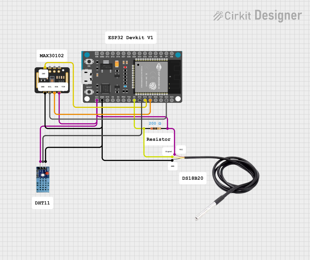
Connecting Peripherals:
- Use the GPIO pins to connect sensors, actuators, or other peripherals.
- Ensure that the voltage levels of connected devices are compatible with the ESP32 (3.3V logic).
Uploading Code:
- Write your code in the Arduino IDE or use example sketches.
- Click the "Upload" button to flash the code to the ESP32.
Example Code: Blinking an LED
The following example demonstrates how to blink an LED connected to GPIO2:
// Define the GPIO pin where the LED is connected
const int ledPin = 2;

void setup() {
  // Set the LED pin as an output
  pinMode(ledPin, OUTPUT);
}

void loop() {
  // Turn the LED on
  digitalWrite(ledPin, HIGH);
  delay(1000); // Wait for 1 second

  // Turn the LED off
  digitalWrite(ledPin, LOW);
  delay(1000); // Wait for 1 second
}
Important Considerations and Best Practices
- Avoid connecting 5V logic devices directly to the GPIO pins, as the ESP32 operates at 3.3V logic levels.
- Use pull-up or pull-down resistors for input pins to ensure stable readings.
- Be cautious with high-current devices; use external transistors or relays if needed.
- Use decoupling capacitors near the power pins to reduce noise in sensitive applications.
Troubleshooting and FAQs
Common Issues and Solutions
The board is not detected by the computer:
- Ensure the USB cable is functional and supports data transfer.
- Install the correct USB-to-serial driver (e.g., CP2102 or CH340).
Code upload fails:
- Check the selected board and port in the Arduino IDE.
- Hold the "BOOT" button on the board while uploading the code.
Wi-Fi connection issues:
- Verify the SSID and password in your code.
- Ensure the router is within range and supports 2.4 GHz Wi-Fi.
GPIO pin not working as expected:
- Check if the pin is reserved for specific functions (e.g., boot mode).
- Avoid using GPIO pins 6-11, as they are connected to the internal flash memory.
FAQs
Q: Can I power the ESP32 DEVKIT V1 with a battery?
A: Yes, you can use a LiPo battery with a voltage regulator or connect it to the VIN pin (7-12V).
Q: How do I reset the board?
A: Press the "EN" button on the board to reset it.
Q: Can I use the ESP32 with MicroPython?
A: Yes, the ESP32 supports MicroPython. You can flash the MicroPython firmware to the board and use it for development.
Q: What is the maximum current output of the 3V3 pin?
A: The 3V3 pin can supply up to 500 mA, depending on the input power source.
By following this documentation, you can effectively use the ESP32 DEVKIT V1 for a wide range of applications.