Cirkit Designer Logo
Cirkit Designer
Your all-in-one circuit design IDE
Home / 
Component Documentation

How to Use 8 Channel Relay JD-VCC: Examples, Pinouts, and Specs

Image of 8 Channel Relay JD-VCC
Cirkit Designer LogoDesign with 8 Channel Relay JD-VCC in Cirkit Designer

Introduction

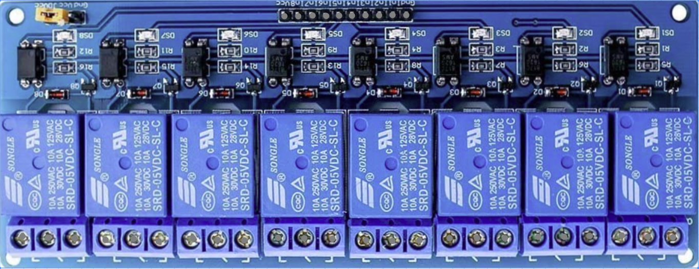
The 8 Channel Relay Module with JD-VCC control signal is a versatile and robust electronic component manufactured by Songle, part number SRD-05VDC-SL-C. This module is designed to interface with microcontrollers such as Arduino, allowing for the control of high-power devices that operate at higher voltages and currents than the microcontroller can handle directly. Common applications include home automation, industrial controls, and switching of AC/DC loads.

Explore Projects Built with 8 Channel Relay JD-VCC

Use Cirkit Designer to design, explore, and prototype these projects online. Some projects support real-time simulation. Click "Open Project" to start designing instantly!
DC-DC Converter and Relay Module Power Distribution System
Image of relay: A project utilizing 8 Channel Relay JD-VCC in a practical application
This circuit consists of a DC-DC converter powering a 6-channel power module, which in turn supplies 5V to a 2-relay module. The power module distributes the converted voltage to the relay module, enabling it to control external devices.
Cirkit Designer LogoOpen Project in Cirkit Designer
ESP32-Powered 8-Channel Relay Controller with Wi-Fi Connectivity
Image of Olimex ESP32-POE2 4Ch X 2 Switches: A project utilizing 8 Channel Relay JD-VCC in a practical application
This circuit features an ESP32 microcontroller connected to an 8-channel relay module. The ESP32 controls the relay channels via its GPIO pins, allowing for the switching of external devices or loads through the relays.
Cirkit Designer LogoOpen Project in Cirkit Designer
ESP32-Powered Wi-Fi Controlled 8-Channel Relay Module
Image of Olimex ESP32-POE2 8Ch Switch and Sensors: A project utilizing 8 Channel Relay JD-VCC in a practical application
This circuit features an ESP32 microcontroller connected to an 8-channel relay module. The ESP32 controls the relay channels via its GPIO pins, allowing it to switch multiple external devices on and off. The ESP32 also provides power to the relay module.
Cirkit Designer LogoOpen Project in Cirkit Designer
Arduino Nano-Based Smart Relay Controller with RS485 Communication
Image of RELAY RS485: A project utilizing 8 Channel Relay JD-VCC in a practical application
This circuit features an Arduino Nano controlling an 8-channel relay module, with each relay channel connected to digital pins D2 through D9. Additionally, the Arduino interfaces with an RS485 module for serial communication, which is connected to an RS485 to USB converter. Power is supplied through an LM2596 step-down module.
Cirkit Designer LogoOpen Project in Cirkit Designer

Explore Projects Built with 8 Channel Relay JD-VCC

Use Cirkit Designer to design, explore, and prototype these projects online. Some projects support real-time simulation. Click "Open Project" to start designing instantly!
Image of relay: A project utilizing 8 Channel Relay JD-VCC in a practical application
DC-DC Converter and Relay Module Power Distribution System
This circuit consists of a DC-DC converter powering a 6-channel power module, which in turn supplies 5V to a 2-relay module. The power module distributes the converted voltage to the relay module, enabling it to control external devices.
Cirkit Designer LogoOpen Project in Cirkit Designer
Image of Olimex ESP32-POE2 4Ch X 2 Switches: A project utilizing 8 Channel Relay JD-VCC in a practical application
ESP32-Powered 8-Channel Relay Controller with Wi-Fi Connectivity
This circuit features an ESP32 microcontroller connected to an 8-channel relay module. The ESP32 controls the relay channels via its GPIO pins, allowing for the switching of external devices or loads through the relays.
Cirkit Designer LogoOpen Project in Cirkit Designer
Image of Olimex ESP32-POE2 8Ch Switch and Sensors: A project utilizing 8 Channel Relay JD-VCC in a practical application
ESP32-Powered Wi-Fi Controlled 8-Channel Relay Module
This circuit features an ESP32 microcontroller connected to an 8-channel relay module. The ESP32 controls the relay channels via its GPIO pins, allowing it to switch multiple external devices on and off. The ESP32 also provides power to the relay module.
Cirkit Designer LogoOpen Project in Cirkit Designer
Image of RELAY RS485: A project utilizing 8 Channel Relay JD-VCC in a practical application
Arduino Nano-Based Smart Relay Controller with RS485 Communication
This circuit features an Arduino Nano controlling an 8-channel relay module, with each relay channel connected to digital pins D2 through D9. Additionally, the Arduino interfaces with an RS485 module for serial communication, which is connected to an RS485 to USB converter. Power is supplied through an LM2596 step-down module.
Cirkit Designer LogoOpen Project in Cirkit Designer

Technical Specifications

General Features

  • Relay Type: Electromechanical
  • Number of Channels: 8
  • Control Signal: JD-VCC
  • Switching Voltage: Up to 250VAC or 30VDC
  • Current Rating: Up to 10A per channel
  • Operating Voltage: 5VDC for the relay coil
  • Indicator LEDs: LED for each channel indicates relay status

Pin Configuration and Descriptions

Pin Number Description Notes
1 GND Ground
2 IN1 Input signal for Relay 1
3 IN2 Input signal for Relay 2
... ... ...
8 IN8 Input signal for Relay 8
9 VCC 5V power supply for the module
10 JD-VCC External power for relay coils

Note: The JD-VCC pin allows for separate power supply to the relay coils, isolating the control circuit.

Usage Instructions

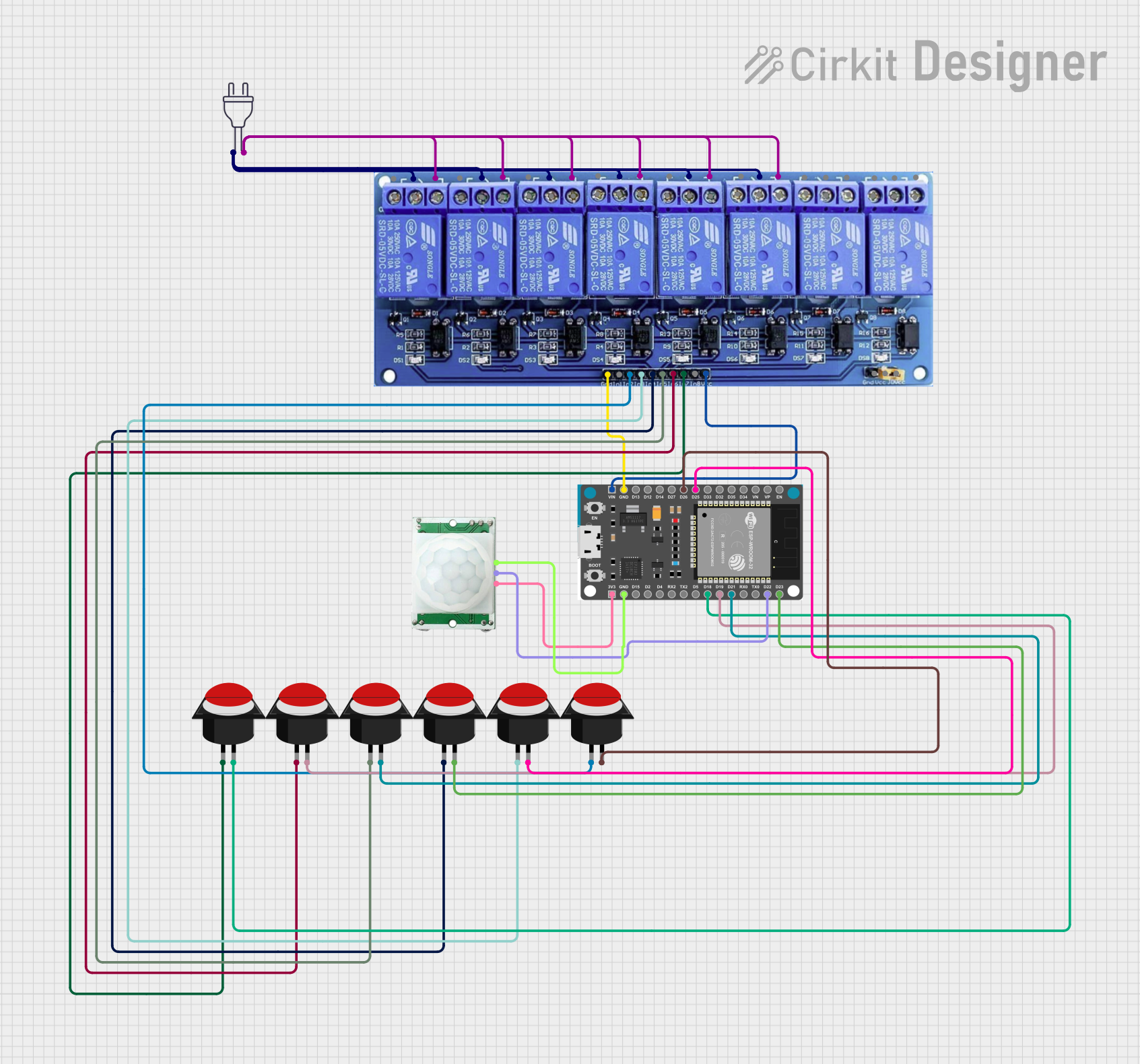
Connecting to a Microcontroller (e.g., Arduino UNO)

  1. Power Connections:

    • Connect the JD-VCC pin to an external 5V power supply if isolation is needed.
    • Connect the VCC pin to the 5V output on the Arduino if JD-VCC is not used.
    • Connect the GND pin to the ground on the Arduino.
  2. Input Signal Connections:

    • Connect IN1 to IN8 to the digital output pins on the Arduino that you will use to control the relays.
  3. Load Connections:

    • Connect the device you want to control to the Normally Open (NO) and Common (COM) terminals of the relay.

Best Practices

  • Always ensure that the power ratings of the devices you are controlling do not exceed the relay's specifications.
  • Use flyback diodes when switching inductive loads to prevent back EMF damage.
  • Ensure proper isolation between the low voltage control circuit and high voltage load circuit.

Example Arduino Code

// Define relay control pins
const int relayPins[] = {2, 3, 4, 5, 6, 7, 8, 9};

void setup() {
  // Initialize all relay control pins as outputs
  for (int i = 0; i < 8; i++) {
    pinMode(relayPins[i], OUTPUT);
    digitalWrite(relayPins[i], HIGH); // Relays are active LOW
  }
}

void loop() {
  // Example: Turn on each relay for 1 second, then off
  for (int i = 0; i < 8; i++) {
    digitalWrite(relayPins[i], LOW); // Activate relay
    delay(1000);                     // Wait for 1 second
    digitalWrite(relayPins[i], HIGH); // Deactivate relay
    delay(1000);                     // Wait for 1 second
  }
}

Note: The relays are active LOW, meaning they are triggered when the input is LOW.

Troubleshooting and FAQs

Common Issues

  • Relay not activating: Check the input signal and power connections. Ensure the control signal is LOW to activate the relay.
  • Intermittent operation: Verify that the power supply can handle the current draw of all relays if activated simultaneously.
  • Noisy operation: Relays produce an audible click when switching. This is normal but can be reduced with solid-state relays if necessary.

FAQs

Q: Can I power the relay module directly from the Arduino 5V pin? A: Yes, if the current draw is within the Arduino's limits. For full 8-channel use, an external power supply is recommended.

Q: How do I know if the relay is on or off? A: The module has an LED indicator for each relay. When the LED is lit, the relay is activated.

Q: Can I use this relay module with a 3.3V microcontroller? A: The input control signal is typically compatible with 3.3V logic; however, ensure that the relay coil is powered with 5V.

Q: What is the purpose of the JD-VCC pin? A: JD-VCC allows you to power the relay coils separately from the microcontroller, providing electrical isolation between the control and power circuits.

For further assistance, consult the manufacturer's datasheet and ensure all connections are secure and correct.