How to Use Waveshare ESP32-S3-ETH-8DI-8RO-C: Examples, Pinouts, and Specs
Introduction
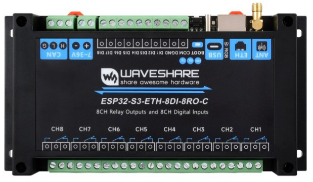
The Waveshare ESP32-S3-ETH-8DI-8RO-C is a powerful and versatile development board designed for Internet of Things (IoT) applications. It is built around the ESP32-S3 chip, which features dual-core Xtensa LX7 processors, Wi-Fi, and Bluetooth 5.0 connectivity. This board is equipped with 8 digital inputs (DI), 8 relay outputs (RO), and Ethernet connectivity, making it ideal for industrial automation, smart home systems, and other IoT projects requiring reliable communication and control.
Explore Projects Built with Waveshare ESP32-S3-ETH-8DI-8RO-C
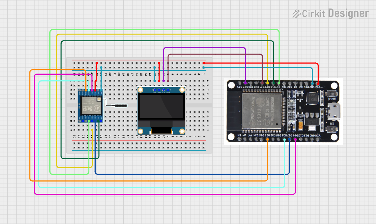
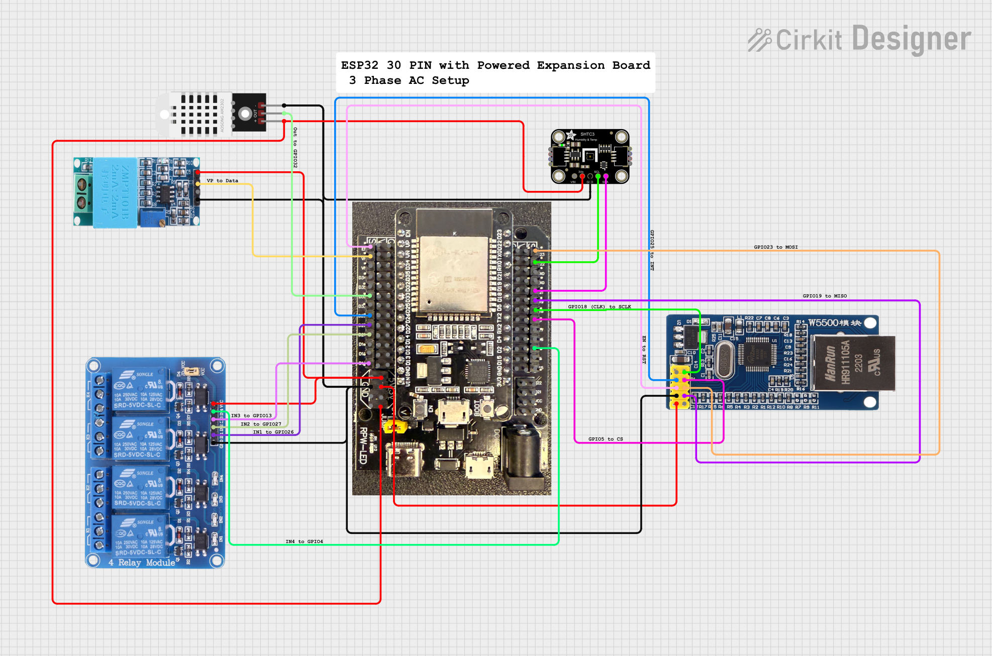

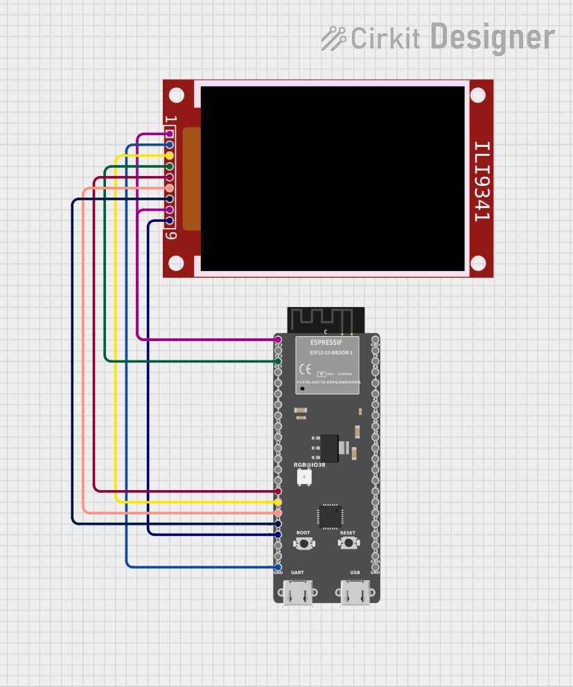
Explore Projects Built with Waveshare ESP32-S3-ETH-8DI-8RO-C
Common Applications and Use Cases
- Industrial automation and control systems
- Smart home devices and automation
- Remote monitoring and data logging
- IoT gateways with Ethernet connectivity
- Projects requiring multiple relay outputs and digital inputs
Technical Specifications
Below are the key technical details of the Waveshare ESP32-S3-ETH-8DI-8RO-C:
General Specifications
| Parameter | Value |
|---|---|
| Microcontroller | ESP32-S3 (Xtensa LX7 dual-core processor) |
| Wireless Connectivity | Wi-Fi 802.11 b/g/n, Bluetooth 5.0 |
| Ethernet | 10/100 Mbps Ethernet |
| Digital Inputs (DI) | 8 channels |
| Relay Outputs (RO) | 8 channels |
| Operating Voltage | 5V (via USB-C) or 7-24V (via terminal) |
| Power Consumption | < 2W (typical, without relays active) |
| Dimensions | 134mm x 84mm |
Pin Configuration and Descriptions
Digital Inputs (DI)
| Pin Number | Label | Description |
|---|---|---|
| DI1 | IN1 | Digital Input 1 |
| DI2 | IN2 | Digital Input 2 |
| DI3 | IN3 | Digital Input 3 |
| DI4 | IN4 | Digital Input 4 |
| DI5 | IN5 | Digital Input 5 |
| DI6 | IN6 | Digital Input 6 |
| DI7 | IN7 | Digital Input 7 |
| DI8 | IN8 | Digital Input 8 |
Relay Outputs (RO)
| Pin Number | Label | Description |
|---|---|---|
| RO1 | OUT1 | Relay Output 1 |
| RO2 | OUT2 | Relay Output 2 |
| RO3 | OUT3 | Relay Output 3 |
| RO4 | OUT4 | Relay Output 4 |
| RO5 | OUT5 | Relay Output 5 |
| RO6 | OUT6 | Relay Output 6 |
| RO7 | OUT7 | Relay Output 7 |
| RO8 | OUT8 | Relay Output 8 |
Power and Communication
| Pin Number | Label | Description |
|---|---|---|
| VIN | VIN | External power input (7-24V) |
| GND | GND | Ground |
| USB-C | USB-C | USB power and programming interface |
| ETH | RJ45 Port | Ethernet connection |
Usage Instructions
How to Use the Component in a Circuit
Powering the Board:
- Connect a 7-24V DC power supply to the VIN and GND terminals, or use a USB-C cable for 5V power.
- Ensure the power supply can provide sufficient current for the relays if they are all active.
Connecting Digital Inputs:
- Connect external sensors or switches to the digital input pins (IN1 to IN8).
- Ensure the input voltage levels are compatible with the ESP32-S3's GPIO pins (3.3V logic).
Using Relay Outputs:
- Connect the devices you want to control (e.g., lights, motors) to the relay output terminals (OUT1 to OUT8).
- Ensure the load does not exceed the relay's maximum current and voltage ratings.
Ethernet Connectivity:
- Connect an Ethernet cable to the RJ45 port for wired network communication.
- Configure the network settings in your firmware to enable Ethernet functionality.
Programming the Board:
- Use the USB-C port to connect the board to your computer.
- Install the necessary drivers and use the Arduino IDE or ESP-IDF to upload your code.
Important Considerations and Best Practices
- Relay Ratings: Ensure the connected load does not exceed the relay's maximum ratings (typically 10A at 250VAC or 30VDC).
- Isolation: Use optocouplers or other isolation techniques if connecting high-voltage devices to the relays.
- Input Protection: Add pull-up or pull-down resistors to the digital inputs if required by your application.
- Firmware Updates: Regularly update the ESP32-S3 firmware to ensure compatibility and security.
Example Code for Arduino IDE
Below is an example code snippet to control the relays and read the digital inputs using the Arduino IDE:
// Include the necessary libraries
#include <WiFi.h>

// Define relay output pins
#define RELAY1  25
#define RELAY2  26
#define RELAY3  27
#define RELAY4  14
#define RELAY5  12
#define RELAY6  13
#define RELAY7  15
#define RELAY8  2

// Define digital input pins
#define INPUT1  32
#define INPUT2  33
#define INPUT3  34
#define INPUT4  35
#define INPUT5  36
#define INPUT6  39
#define INPUT7  21
#define INPUT8  19

void setup() {
  // Initialize serial communication
  Serial.begin(115200);

  // Set relay pins as outputs
  pinMode(RELAY1, OUTPUT);
  pinMode(RELAY2, OUTPUT);
  pinMode(RELAY3, OUTPUT);
  pinMode(RELAY4, OUTPUT);
  pinMode(RELAY5, OUTPUT);
  pinMode(RELAY6, OUTPUT);
  pinMode(RELAY7, OUTPUT);
  pinMode(RELAY8, OUTPUT);

  // Set digital input pins as inputs
  pinMode(INPUT1, INPUT);
  pinMode(INPUT2, INPUT);
  pinMode(INPUT3, INPUT);
  pinMode(INPUT4, INPUT);
  pinMode(INPUT5, INPUT);
  pinMode(INPUT6, INPUT);
  pinMode(INPUT7, INPUT);
  pinMode(INPUT8, INPUT);

  // Turn off all relays initially
  digitalWrite(RELAY1, LOW);
  digitalWrite(RELAY2, LOW);
  digitalWrite(RELAY3, LOW);
  digitalWrite(RELAY4, LOW);
  digitalWrite(RELAY5, LOW);
  digitalWrite(RELAY6, LOW);
  digitalWrite(RELAY7, LOW);
  digitalWrite(RELAY8, LOW);
}

void loop() {
  // Read digital inputs and print their states
  Serial.print("Input 1: "); Serial.println(digitalRead(INPUT1));
  Serial.print("Input 2: "); Serial.println(digitalRead(INPUT2));
  Serial.print("Input 3: "); Serial.println(digitalRead(INPUT3));
  Serial.print("Input 4: "); Serial.println(digitalRead(INPUT4));
  Serial.print("Input 5: "); Serial.println(digitalRead(INPUT5));
  Serial.print("Input 6: "); Serial.println(digitalRead(INPUT6));
  Serial.print("Input 7: "); Serial.println(digitalRead(INPUT7));
  Serial.print("Input 8: "); Serial.println(digitalRead(INPUT8));

  // Example: Toggle relay 1 based on input 1
  if (digitalRead(INPUT1) == HIGH) {
    digitalWrite(RELAY1, HIGH); // Turn on relay 1
  } else {
    digitalWrite(RELAY1, LOW);  // Turn off relay 1
  }

  delay(1000); // Wait for 1 second
}
Troubleshooting and FAQs
Common Issues and Solutions
Relays Not Activating:
- Ensure the board is powered with sufficient voltage and current.
- Check the relay control pins in your code and ensure they are set as outputs.
Digital Inputs Not Responding:
- Verify the input voltage levels are within the acceptable range (3.3V logic).
- Check for loose connections or faulty sensors.
Ethernet Not Working:
- Ensure the Ethernet cable is securely connected to the RJ45 port.
- Verify the network settings in your firmware (e.g., IP address, subnet mask).
Board Not Detected by Computer:
- Install the correct USB drivers for the ESP32-S3.
- Try a different USB cable or port.
FAQs
- Can I use this board with the Arduino IDE?
Yes, the board is compatible with the Arduino IDE. Install the ESP32 board package to get started.