How to Use ESP32 38-pin Expansion Board: Examples, Pinouts, and Specs
Introduction
The ESP32 38-pin Expansion Board, manufactured by Espressif (Part ID: ESP32), is a versatile and user-friendly development board designed to simplify prototyping and development with the ESP32 microcontroller. Featuring 38 GPIO pins, this board provides seamless connectivity to a wide range of sensors, modules, and peripherals, making it an ideal choice for Internet of Things (IoT) applications, smart devices, and embedded systems.
Explore Projects Built with ESP32 38-pin Expansion Board

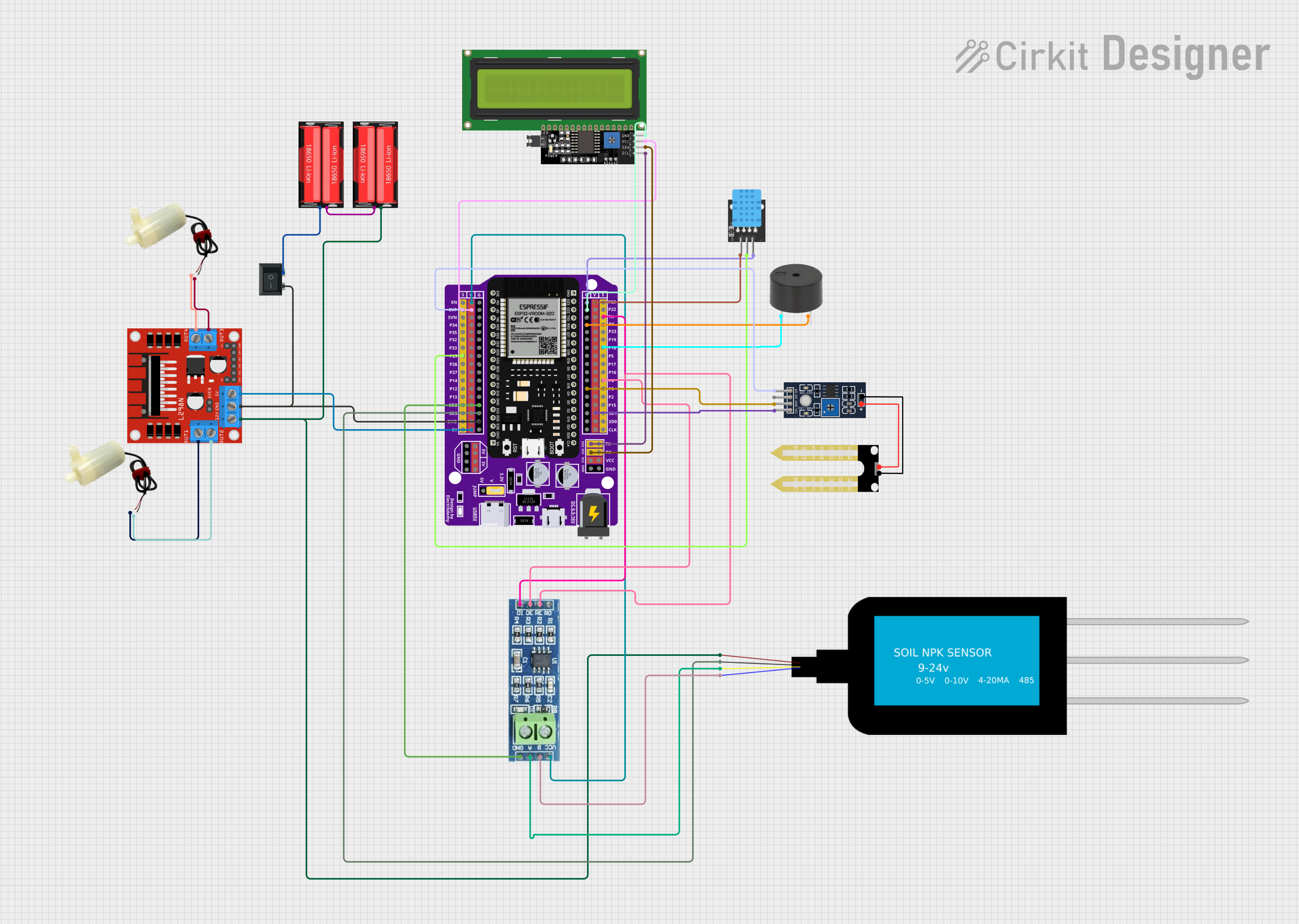
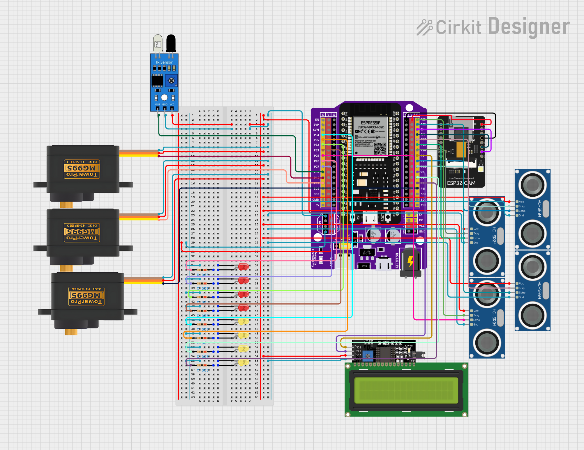

Explore Projects Built with ESP32 38-pin Expansion Board
Common Applications and Use Cases
- IoT devices and smart home automation
- Wireless communication projects (Wi-Fi and Bluetooth)
- Sensor data acquisition and processing
- Robotics and motor control
- Prototyping and educational projects
Technical Specifications
The ESP32 38-pin Expansion Board is built to support the powerful ESP32 microcontroller, offering robust performance and connectivity options. Below are the key technical details:
Key Technical Details
- Microcontroller: ESP32 dual-core processor
- Operating Voltage: 3.3V
- Input Voltage (via USB): 5V
- Wi-Fi Standard: 802.11 b/g/n
- Bluetooth: BLE (Bluetooth Low Energy) and Bluetooth Classic
- GPIO Pins: 38 (configurable for digital I/O, PWM, ADC, DAC, etc.)
- ADC Channels: Up to 18 (12-bit resolution)
- DAC Channels: 2
- PWM Channels: 16
- Flash Memory: 4MB
- Communication Interfaces: UART, SPI, I2C, I2S
- USB Interface: Micro-USB for programming and power
- Operating Temperature: -40°C to +85°C
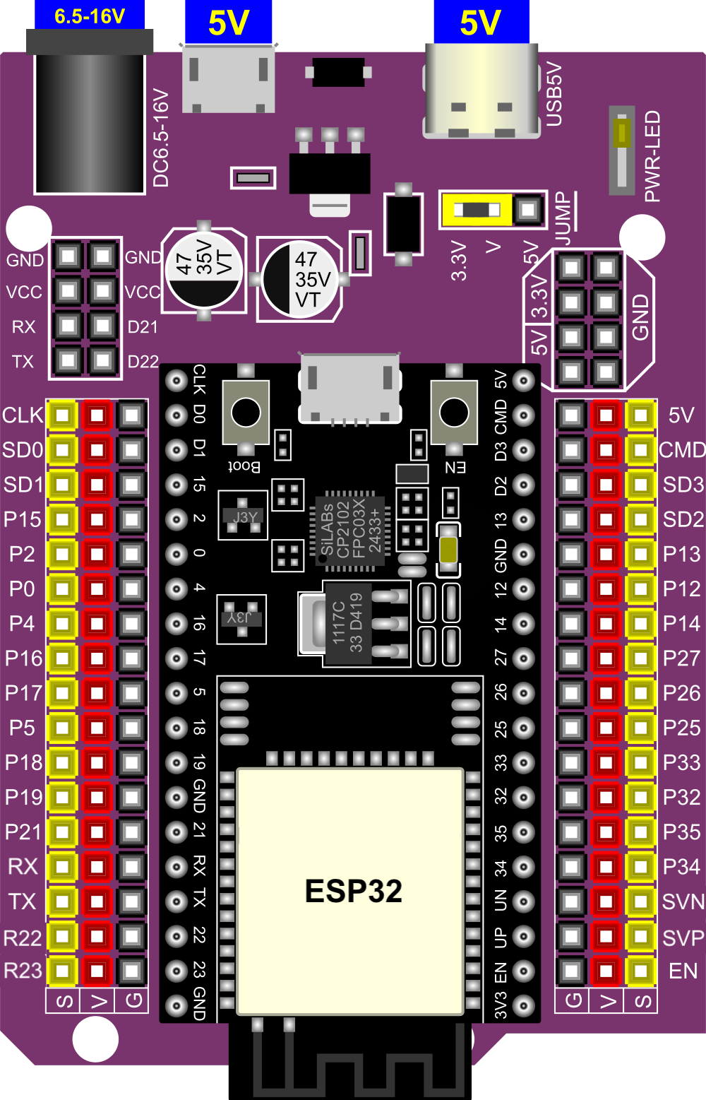
Pin Configuration and Descriptions
The ESP32 38-pin Expansion Board features a 38-pin layout, with each pin serving a specific function. Below is a detailed pinout description:
| Pin Number | Pin Name | Function | Description |
|---|---|---|---|
| 1-3 | GND | Ground | Common ground for the circuit. |
| 4 | 3V3 | Power Supply | 3.3V output for powering external components. |
| 5 | EN | Enable | Active-high pin to enable the ESP32 chip. |
| 6-7 | IO0, IO2 | GPIO | General-purpose input/output pins. |
| 8-9 | IO4, IO5 | GPIO, PWM | Configurable as digital I/O or PWM output. |
| 10-11 | IO12, IO13 | GPIO, ADC | Configurable as digital I/O or analog input. |
| 12-13 | IO14, IO15 | GPIO, PWM | Configurable as digital I/O or PWM output. |
| 14-15 | IO16, IO17 | GPIO, UART | Configurable as digital I/O or UART communication pins. |
| 16-17 | IO18, IO19 | GPIO, SPI | Configurable as digital I/O or SPI communication pins. |
| 18-19 | IO21, IO22 | GPIO, I2C | Configurable as digital I/O or I2C communication pins. |
| 20-21 | IO23, IO25 | GPIO, DAC | Configurable as digital I/O or DAC output. |
| 22-23 | IO26, IO27 | GPIO, ADC | Configurable as digital I/O or analog input. |
| 24-25 | IO32, IO33 | GPIO, ADC | Configurable as digital I/O or analog input. |
| 26-27 | IO34, IO35 | GPIO, ADC | Input-only pins, configurable as analog input. |
| 28-29 | IO36, IO39 | GPIO, ADC | Input-only pins, configurable as analog input. |
| 30 | VIN | Power Input | External power input (5V). |
| 31-38 | Other Pins | Various | Includes additional GPIO, UART, and SPI pins. |
Usage Instructions
The ESP32 38-pin Expansion Board is designed for ease of use, making it suitable for both beginners and experienced developers. Follow the steps below to get started:
How to Use the Component in a Circuit
Powering the Board:
- Connect the board to your computer using a Micro-USB cable for power and programming.
- Alternatively, supply 5V to the VIN pin for external power.
Programming the Board:
- Install the ESP32 board package in the Arduino IDE or use the Espressif IDF (IoT Development Framework).
- Select the correct board and port in the IDE settings.
Connecting Peripherals:
- Use the GPIO pins to connect sensors, actuators, or other modules.
- Ensure that the voltage levels of connected devices are compatible with the 3.3V logic of the ESP32.
Uploading Code:
- Write your code in the Arduino IDE or another supported environment.
- Press the "Upload" button to flash the code to the ESP32.
Important Considerations and Best Practices
- Voltage Levels: The ESP32 operates at 3.3V logic. Avoid connecting 5V devices directly to GPIO pins without a level shifter.
- Pin Multiplexing: Many pins have multiple functions (e.g., ADC, UART, SPI). Configure them carefully in your code.
- Boot Mode: Ensure that IO0 is pulled low during programming to enter boot mode.
- Power Supply: Use a stable power source to avoid unexpected resets or performance issues.
Example Code for Arduino UNO Integration
Below is an example of how to use the ESP32 38-pin Expansion Board to read data from a DHT11 temperature and humidity sensor:
#include "DHT.h"

// Define the DHT sensor type and pin
#define DHTPIN 4       // GPIO4 is connected to the DHT11 data pin
#define DHTTYPE DHT11  // DHT11 sensor type

DHT dht(DHTPIN, DHTTYPE);

void setup() {
  Serial.begin(115200);  // Initialize serial communication
  dht.begin();           // Initialize the DHT sensor
  Serial.println("DHT11 Sensor Test");
}

void loop() {
  float temperature = dht.readTemperature();  // Read temperature in Celsius
  float humidity = dht.readHumidity();        // Read humidity percentage

  // Check if the readings are valid
  if (isnan(temperature) || isnan(humidity)) {
    Serial.println("Failed to read from DHT sensor!");
    return;
  }

  // Print the readings to the Serial Monitor
  Serial.print("Temperature: ");
  Serial.print(temperature);
  Serial.println(" °C");
  Serial.print("Humidity: ");
  Serial.print(humidity);
  Serial.println(" %");

  delay(2000);  // Wait 2 seconds before the next reading
}
Troubleshooting and FAQs
Common Issues Users Might Face
Board Not Detected by Computer:
- Ensure the USB cable is functional and supports data transfer.
- Install the correct USB-to-serial driver for the ESP32.
Code Upload Fails:
- Check that the correct board and port are selected in the IDE.
- Hold the "BOOT" button on the board while uploading the code.
Unstable Operation:
- Verify that the power supply is stable and sufficient.
- Avoid using GPIO pins for high-current loads without proper drivers.
Solutions and Tips for Troubleshooting
- Debugging Tools: Use the Serial Monitor to print debug messages and identify issues in your code.
- Resetting the Board: Press the "EN" button to reset the ESP32 if it becomes unresponsive.
- Pin Conflicts: Double-check pin assignments in your code to avoid conflicts with default functions.
By following this documentation, you can effectively utilize the ESP32 38-pin Expansion Board for your IoT and embedded system projects.