
How to Use ESP32 WROOM 32: Examples, Pinouts, and Specs
 Design with ESP32 WROOM 32 in Cirkit Designer
Introduction
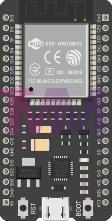
The ESP32 WROOM 32, manufactured by Microcontroller (Part ID: ESP32), is a powerful and versatile microcontroller module designed for a wide range of applications. It features integrated Wi-Fi and Bluetooth capabilities, making it an excellent choice for Internet of Things (IoT) projects, wireless communication systems, and smart devices. With its dual-core processor, low power consumption, and extensive GPIO options, the ESP32 WROOM 32 is suitable for both hobbyists and professional developers.
Explore Projects Built with ESP32 WROOM 32
 Open Project in Cirkit Designer
 Open Project in Cirkit Designer
 Open Project in Cirkit Designer
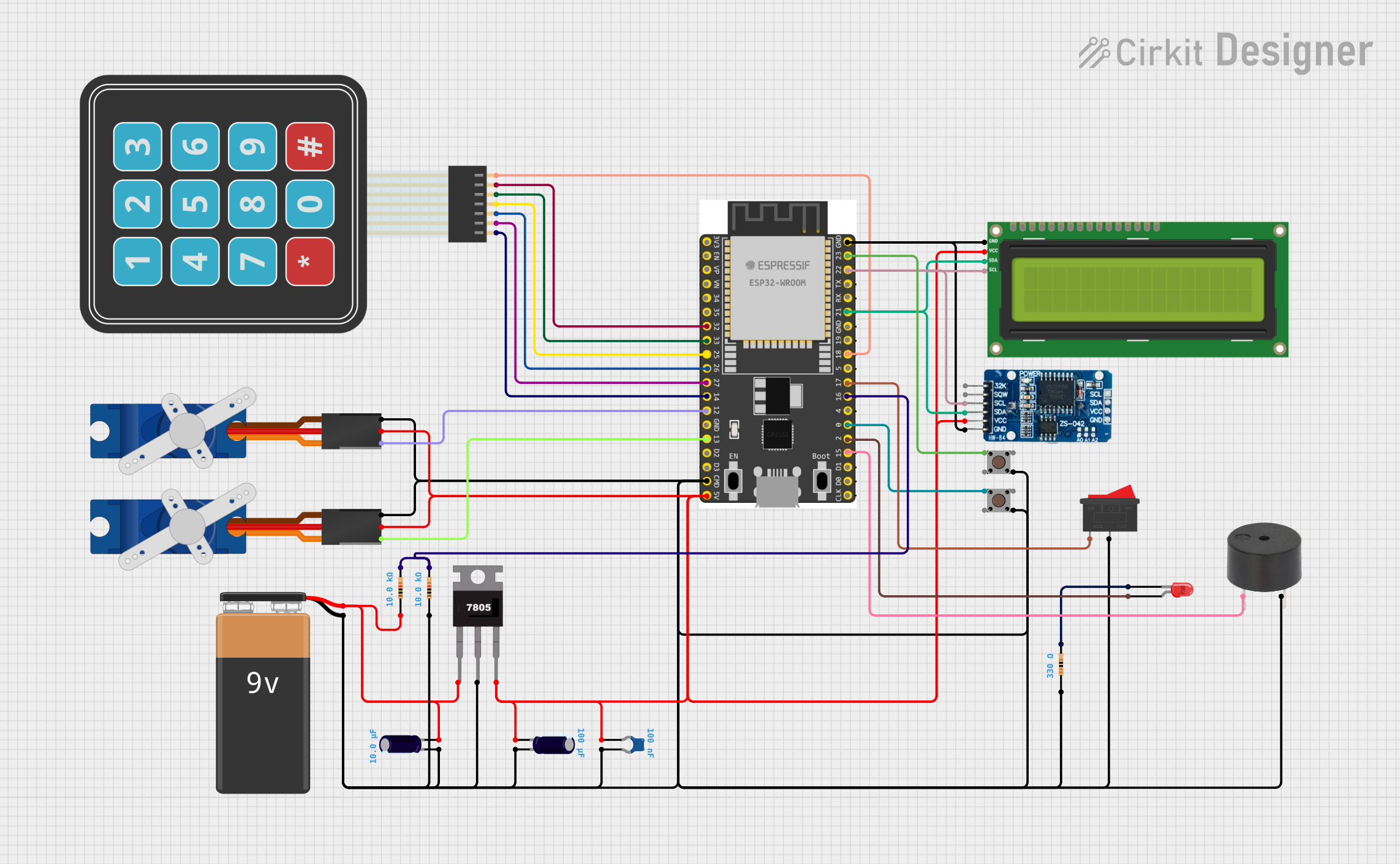 Open Project in Cirkit Designer
Explore Projects Built with ESP32 WROOM 32
Open Project in Cirkit DesignerOpen Project in Cirkit DesignerOpen Project in Cirkit DesignerOpen Project in Cirkit DesignerCommon Applications and Use Cases
- IoT devices and smart home automation
- Wireless sensor networks
- Wearable technology
- Industrial automation and control systems
- Robotics and drones
- Real-time data monitoring and logging
Technical Specifications
The ESP32 WROOM 32 module is built for high performance and flexibility. Below are its key technical details:
Key Technical Details
| Parameter | Specification |
|---|---|
| Microcontroller | Tensilica Xtensa LX6 dual-core CPU |
| Clock Speed | Up to 240 MHz |
| Flash Memory | 4 MB (external SPI flash) |
| SRAM | 520 KB |
| Wi-Fi | 802.11 b/g/n (2.4 GHz) |
| Bluetooth | v4.2 BR/EDR and BLE |
| Operating Voltage | 3.3 V |
| Input Voltage Range | 3.0 V to 3.6 V |
| GPIO Pins | 34 |
| ADC Channels | 18 (12-bit resolution) |
| DAC Channels | 2 |
| UART Interfaces | 3 |
| SPI Interfaces | 4 |
| I2C Interfaces | 2 |
| PWM Channels | 16 |
| Power Consumption | Ultra-low power (deep sleep: ~10 µA) |
Pin Configuration and Descriptions
The ESP32 WROOM 32 module has 38 pins. Below is a table summarizing the key pin functions:
| Pin Number | Pin Name | Description |
|---|---|---|
| 1 | EN | Enable pin (active high) |
| 2 | IO0 | GPIO0, used for boot mode selection |
| 3 | IO1 (TX0) | GPIO1, UART0 TX |
| 4 | IO3 (RX0) | GPIO3, UART0 RX |
| 5 | IO4 | GPIO4, general-purpose I/O |
| 6 | IO5 | GPIO5, general-purpose I/O |
| 7 | IO12 | GPIO12, ADC2 channel 5 |
| 8 | IO13 | GPIO13, ADC2 channel 4 |
| 9 | IO14 | GPIO14, ADC2 channel 6 |
| 10 | IO15 | GPIO15, ADC2 channel 3 |
| 11 | IO16 | GPIO16, general-purpose I/O |
| 12 | IO17 | GPIO17, general-purpose I/O |
| 13 | IO18 | GPIO18, SPI clock (SCK) |
| 14 | IO19 | GPIO19, SPI master-out/slave-in (MOSI) |
| 15 | IO21 | GPIO21, I2C SDA |
| 16 | IO22 | GPIO22, I2C SCL |
| 17 | IO23 | GPIO23, SPI master-in/slave-out (MISO) |
| 18 | GND | Ground |
| 19 | 3V3 | 3.3 V power supply |
For a complete pinout, refer to the ESP32 WROOM 32 datasheet.
Usage Instructions
The ESP32 WROOM 32 is easy to integrate into a variety of projects. Below are the steps and best practices for using the module effectively.
How to Use the ESP32 WROOM 32 in a Circuit
- Power Supply: Ensure the module is powered with a stable 3.3 V supply. Avoid exceeding the maximum input voltage of 3.6 V.
- Boot Mode: To upload code, connect GPIO0 to GND during boot. This puts the ESP32 into programming mode.
- GPIO Usage: Use GPIO pins for interfacing with sensors, actuators, and other peripherals. Be mindful of pins with special functions (e.g., ADC, DAC, UART).
- Wi-Fi and Bluetooth: Configure the Wi-Fi and Bluetooth settings in your code to enable wireless communication.
- Programming: Use the Arduino IDE or ESP-IDF (Espressif IoT Development Framework) to write and upload code.
Important Considerations and Best Practices
- Voltage Levels: The ESP32 operates at 3.3 V logic levels. Use level shifters if interfacing with 5 V devices.
- Deep Sleep Mode: Utilize the deep sleep mode to minimize power consumption in battery-powered applications.
- Antenna Placement: Ensure the onboard antenna has sufficient clearance from metal objects to avoid signal interference.
- Heat Management: The ESP32 can get warm during operation. Provide adequate ventilation if used in enclosed spaces.
Example Code for Arduino UNO Integration
Below is an example of using the ESP32 WROOM 32 to connect to a Wi-Fi network and send data to a server:
#include <WiFi.h> // Include the Wi-Fi library

// Replace with your network credentials
const char* ssid = "Your_SSID";
const char* password = "Your_PASSWORD";

void setup() {
  Serial.begin(115200); // Initialize serial communication at 115200 baud
  delay(1000);

  // Connect to Wi-Fi
  Serial.println("Connecting to Wi-Fi...");
  WiFi.begin(ssid, password);

  while (WiFi.status() != WL_CONNECTED) {
    delay(500);
    Serial.print("."); // Print dots while connecting
  }

  Serial.println("\nWi-Fi connected!");
  Serial.print("IP Address: ");
  Serial.println(WiFi.localIP()); // Print the assigned IP address
}

void loop() {
  // Add your main code here
}
Troubleshooting and FAQs
Common Issues and Solutions
- ESP32 Not Connecting to Wi-Fi
- Solution: Double-check the SSID and password. Ensure the router is within range and supports 2.4 GHz Wi-Fi.
- Code Upload Fails
- Solution: Ensure GPIO0 is connected to GND during boot. Check the USB cable and port.
- Module Overheating
- Solution: Reduce the clock speed or provide better ventilation.
- Unstable Power Supply
- Solution: Use a low-noise, regulated 3.3 V power source.
FAQs
- Can the ESP32 WROOM 32 operate on 5 V?
- No, the module operates at 3.3 V. Use a voltage regulator or level shifter for 5 V systems.
- How do I reset the ESP32?
- Press the EN (enable) button on the module to reset it.
- Can I use the ESP32 with the Arduino IDE?
- Yes, the ESP32 is fully compatible with the Arduino IDE. Install the ESP32 board package to get started.
This concludes the documentation for the ESP32 WROOM 32. For further details, refer to the official datasheet and user manual.