
How to Use 9 Port DIN POE++ Switch with 10gb SFP+: Examples, Pinouts, and Specs
 Design with 9 Port DIN POE++ Switch with 10gb SFP+ in Cirkit Designer
Introduction
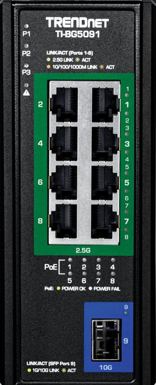
The TrendNet TI-BG5091 is an industrial-grade network switch designed to deliver both power and data connectivity to networked devices. Equipped with 9 Gigabit PoE++ ports and a 10Gb SFP+ slot, this switch is ideal for high-performance networking in environments requiring robust and reliable connections. Its Power over Ethernet (PoE++) capability allows it to power devices such as IP cameras, VoIP phones, and wireless access points, eliminating the need for separate power supplies.
Explore Projects Built with 9 Port DIN POE++ Switch with 10gb SFP+
 Open Project in Cirkit Designer
 Open Project in Cirkit Designer
 Open Project in Cirkit Designer
 Open Project in Cirkit Designer
Explore Projects Built with 9 Port DIN POE++ Switch with 10gb SFP+
Open Project in Cirkit DesignerOpen Project in Cirkit DesignerOpen Project in Cirkit DesignerOpen Project in Cirkit DesignerCommon Applications and Use Cases
- Surveillance Systems: Powering and connecting IP cameras in industrial or outdoor environments.
- Wireless Networks: Providing data and power to wireless access points.
- VoIP Systems: Supporting VoIP phones in office or industrial setups.
- Industrial Networking: Connecting and powering devices in factories, warehouses, or other rugged environments.
- High-Speed Fiber Connectivity: Utilizing the 10Gb SFP+ port for long-distance, high-speed data transfer.
Technical Specifications
Key Technical Details
| Specification | Value |
|---|---|
| Manufacturer | TrendNet |
| Model | TI-BG5091 |
| Ports | 8 x Gigabit PoE++ (802.3bt), 1 x Gigabit |
| Ethernet, 1 x 10Gb SFP+ | |
| PoE Standards | IEEE 802.3af/at/bt |
| PoE Power Budget | 360W |
| Switching Capacity | 62Gbps |
| Input Voltage | 48-56V DC |
| Operating Temperature | -40°C to 75°C (-40°F to 167°F) |
| Mounting | DIN-Rail or Wall-Mountable |
| Dimensions | 160 x 120 x 60 mm (6.3 x 4.7 x 2.4 in) |
| Weight | 1.5 kg (3.3 lbs) |
| Certifications | CE, FCC, IEC 61000-6-2, IEC 61000-6-4 |
Pin Configuration and Descriptions
PoE++ Ports (1-8)
| Pin Number | Description |
|---|---|
| 1 | Data Pair 1 (Positive) |
| 2 | Data Pair 1 (Negative) |
| 3 | Data Pair 2 (Positive) |
| 4 | Power Pair 1 (Positive) |
| 5 | Power Pair 1 (Positive) |
| 6 | Data Pair 2 (Negative) |
| 7 | Power Pair 2 (Negative) |
| 8 | Power Pair 2 (Negative) |
10Gb SFP+ Port
| Pin Number | Description |
|---|---|
| 1 | Transmit Data (TX) |
| 2 | Receive Data (RX) |
| 3-20 | Reserved for SFP+ module use |
Usage Instructions
How to Use the TI-BG5091 in a Network
Powering the Switch:
- Connect a 48-56V DC power supply to the terminal block on the switch.
- Ensure the power source meets the required voltage and current ratings.
Connecting Devices:
- Use Ethernet cables to connect PoE-compatible devices (e.g., IP cameras, access points) to the PoE++ ports (1-8).
- For non-PoE devices, use the standard Gigabit Ethernet port (port 9).
Fiber Connectivity:
- Insert a compatible 10Gb SFP+ module into the SFP+ slot.
- Connect the fiber optic cable to the SFP+ module for high-speed data transfer.
Mounting:
- Use the included DIN-rail or wall-mount brackets to securely install the switch in the desired location.
Important Considerations and Best Practices
- PoE Power Budget: Ensure the total power consumption of connected devices does not exceed the 360W PoE power budget.
- Cable Quality: Use high-quality Cat5e or Cat6 cables for optimal performance and to minimize signal loss.
- Environmental Conditions: Operate the switch within the specified temperature range (-40°C to 75°C) to avoid damage.
- SFP+ Module Compatibility: Use TrendNet-certified SFP+ modules for guaranteed compatibility and performance.
Example: Connecting to an Arduino UNO via Ethernet
To connect an Arduino UNO to the TI-BG5091 for network communication, you can use an Ethernet shield. Below is an example Arduino sketch for basic communication:
#include <SPI.h>
#include <Ethernet.h>

// MAC address and IP address for the Arduino
byte mac[] = { 0xDE, 0xAD, 0xBE, 0xEF, 0xFE, 0xED };
IPAddress ip(192, 168, 1, 177);

// Initialize the Ethernet server on port 80
EthernetServer server(80);

void setup() {
  // Start the Ethernet connection
  Ethernet.begin(mac, ip);

  // Start the server
  server.begin();
  Serial.begin(9600);
  Serial.println("Server is ready at IP: ");
  Serial.println(Ethernet.localIP());
}

void loop() {
  // Listen for incoming clients
  EthernetClient client = server.available();
  if (client) {
    Serial.println("New client connected");
    while (client.connected()) {
      if (client.available()) {
        char c = client.read();
        Serial.write(c); // Echo data to Serial Monitor
        // Respond to the client
        client.println("Hello from Arduino!");
      }
    }
    client.stop();
    Serial.println("Client disconnected");
  }
}
Troubleshooting and FAQs
Common Issues
No Power to Connected Devices:
- Cause: Insufficient power supply or exceeded PoE power budget.
- Solution: Verify the power supply voltage and ensure the total power consumption of connected devices is within the 360W limit.
No Network Connectivity:
- Cause: Faulty cables or incorrect port connections.
- Solution: Check all Ethernet cables and ensure devices are connected to the correct ports.
SFP+ Module Not Detected:
- Cause: Incompatible or improperly seated SFP+ module.
- Solution: Use a TrendNet-certified SFP+ module and ensure it is securely inserted.
Overheating:
- Cause: Operating outside the specified temperature range.
- Solution: Install the switch in a well-ventilated area within the -40°C to 75°C range.
FAQs
Q: Can I use this switch with non-PoE devices?
- A: Yes, the switch supports non-PoE devices via the standard Gigabit Ethernet port or PoE++ ports without supplying power.
Q: What type of SFP+ modules are compatible?
- A: TrendNet-certified 10Gb SFP+ modules are recommended for optimal performance.
Q: Is the switch suitable for outdoor use?
- A: While the switch is designed for industrial environments, it should be housed in a weatherproof enclosure for outdoor use.
Q: Can I daisy-chain multiple switches?
- A: Yes, you can use the 10Gb SFP+ port to connect multiple switches for extended networks.
This concludes the documentation for the TrendNet TI-BG5091. For further assistance, refer to the official user manual or contact TrendNet support.