
How to Use Intel Edison Mini Breakout Board: Examples, Pinouts, and Specs
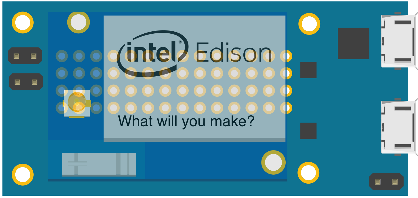
 Design with Intel Edison Mini Breakout Board in Cirkit Designer
Introduction
The Intel Edison Mini Breakout Board is a compact development platform designed to simplify prototyping and development for Internet of Things (IoT) applications. It features the Intel Edison module and provides easy access to its GPIO, I2C, SPI, UART, and other interfaces. This board is ideal for developers looking to integrate sensors, actuators, and other peripherals into their IoT projects.
Explore Projects Built with Intel Edison Mini Breakout Board
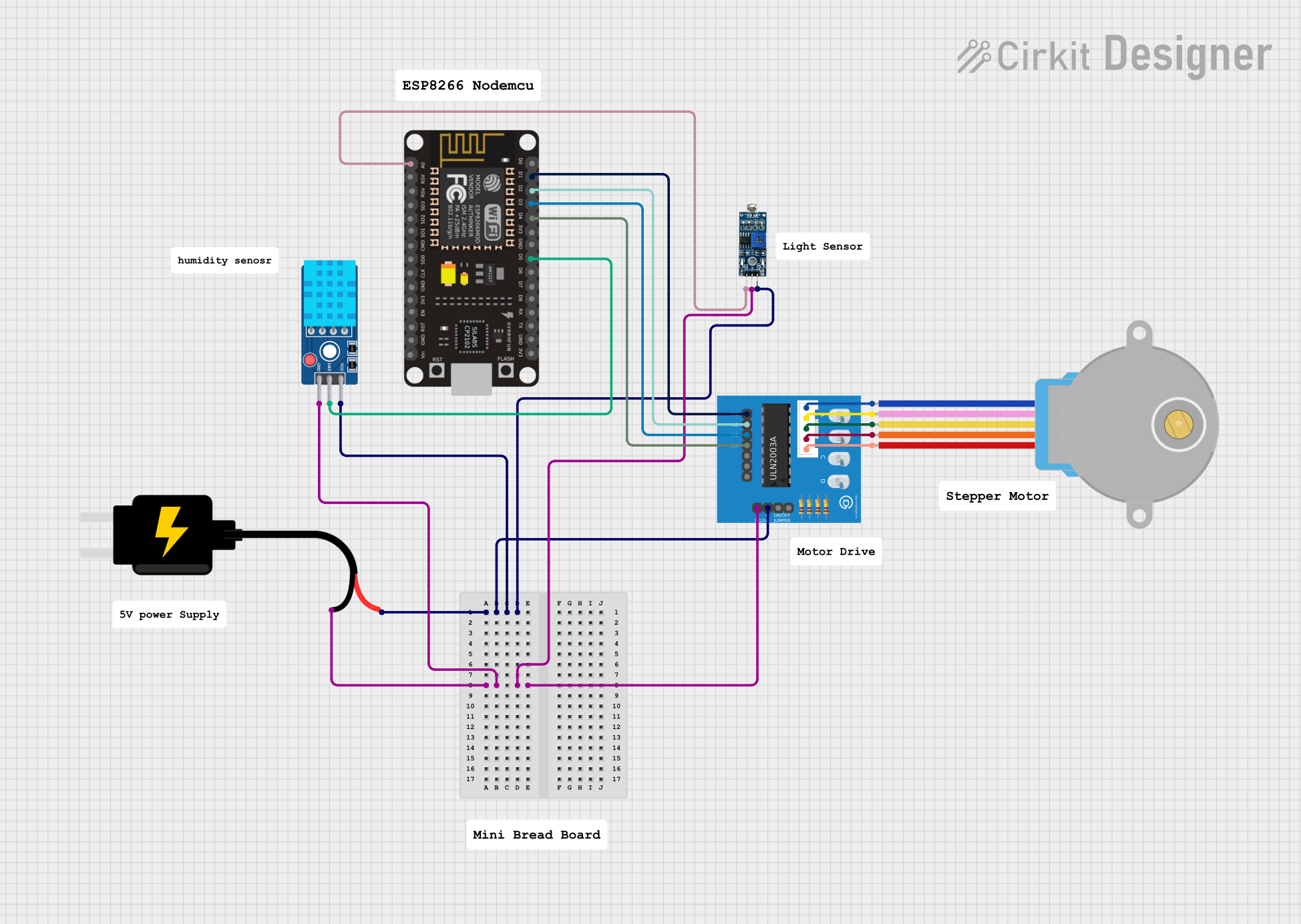 Open Project in Cirkit Designer
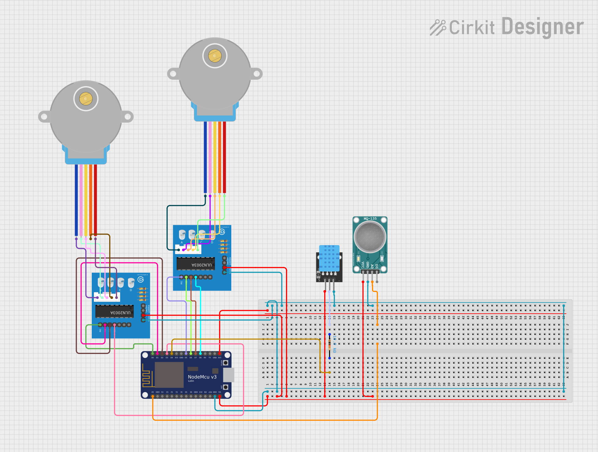 Open Project in Cirkit Designer
 Open Project in Cirkit Designer
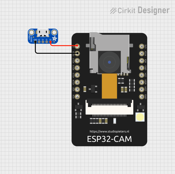 Open Project in Cirkit Designer
Explore Projects Built with Intel Edison Mini Breakout Board
Open Project in Cirkit DesignerOpen Project in Cirkit DesignerOpen Project in Cirkit DesignerOpen Project in Cirkit DesignerCommon Applications and Use Cases
- IoT device prototyping
- Wearable technology development
- Smart home automation systems
- Robotics and sensor integration
- Data logging and monitoring systems
Technical Specifications
Key Technical Details
- Processor: Intel Atom SoC dual-core, dual-threaded at 500 MHz
- RAM: 1 GB LPDDR3
- Storage: 4 GB eMMC
- Connectivity: Wi-Fi (802.11 a/b/g/n), Bluetooth 4.0
- Input Voltage: 7-15 V DC (via external power supply) or 3.3 V (via pin headers)
- GPIO Voltage Levels: 1.8 V logic
- Interfaces: GPIO, I2C, SPI, UART, PWM, ADC
- Dimensions: 35.5 mm x 25 mm
Pin Configuration and Descriptions
The Intel Edison Mini Breakout Board provides access to the following pins:
| Pin Name | Type | Description |
|---|---|---|
| GND | Power | Ground connection |
| 3.3V | Power | 3.3 V power output |
| 5V | Power | 5 V power output (when powered via external supply) |
| GPIOxx | Digital I/O | General-purpose input/output pins (1.8 V logic level) |
| I2C_SCL | Digital Output | I2C clock line |
| I2C_SDA | Digital I/O | I2C data line |
| SPI_MOSI | Digital Output | SPI Master Out Slave In |
| SPI_MISO | Digital Input | SPI Master In Slave Out |
| SPI_SCK | Digital Output | SPI clock line |
| UART_TX | Digital Output | UART transmit line |
| UART_RX | Digital Input | UART receive line |
| PWMxx | Digital Output | Pulse-width modulation output |
| ADCxx | Analog Input | Analog-to-digital converter input (1.8 V max) |
Note: The GPIO pins operate at 1.8 V logic levels. Use level shifters when interfacing with devices that operate at higher voltage levels (e.g., 3.3 V or 5 V).
Usage Instructions
How to Use the Component in a Circuit
Powering the Board:
- Connect an external power supply (7-15 V DC) to the power input jack, or provide 3.3 V directly to the 3.3V pin.
- Ensure the power supply is stable and within the specified voltage range.
Connecting Peripherals:
- Use the GPIO pins to connect sensors, actuators, or other devices. Remember to use level shifters if the peripheral operates at a voltage higher than 1.8 V.
- For communication protocols like I2C, SPI, or UART, connect the corresponding pins (e.g., I2C_SCL and I2C_SDA for I2C).
Programming the Board:
- Connect the board to your computer via USB.
- Use the Arduino IDE, Intel XDK, or other compatible development environments to write and upload code.
Example Circuit:
- Connect an LED to a GPIO pin (e.g., GPIO13) with a current-limiting resistor.
- Write a program to toggle the LED on and off.
Important Considerations and Best Practices
- Always check the voltage levels of connected peripherals to avoid damaging the board.
- Use proper grounding to ensure stable operation and reduce noise in the circuit.
- Avoid drawing excessive current from the GPIO pins (maximum 4 mA per pin).
- For Wi-Fi and Bluetooth functionality, ensure the board has a clear line of sight to minimize interference.
Example Code for Arduino IDE
The following example demonstrates how to blink an LED connected to GPIO13:
// Define the GPIO pin for the LED
const int ledPin = 13;

void setup() {
  // Set the LED pin as an output
  pinMode(ledPin, OUTPUT);
}

void loop() {
  // Turn the LED on
  digitalWrite(ledPin, HIGH);
  delay(1000); // Wait for 1 second

  // Turn the LED off
  digitalWrite(ledPin, LOW);
  delay(1000); // Wait for 1 second
}
Note: Ensure the GPIO pin number matches the physical pin used on the board.
Troubleshooting and FAQs
Common Issues and Solutions
Board Not Powering On:
- Verify the power supply voltage is within the specified range (7-15 V DC or 3.3 V).
- Check all power connections for loose wires or poor contact.
Unable to Upload Code:
- Ensure the board is properly connected to your computer via USB.
- Install the necessary drivers for the Intel Edison module.
- Check that the correct board and port are selected in the Arduino IDE.
Peripherals Not Responding:
- Confirm the wiring is correct and matches the pin configuration.
- Check the voltage levels of connected peripherals and use level shifters if needed.
- Verify that the code initializes the communication protocol (e.g., I2C or SPI) correctly.
Wi-Fi or Bluetooth Not Working:
- Ensure the board is in range of the Wi-Fi network or Bluetooth device.
- Check the network credentials or pairing settings in your code.
FAQs
Q: Can I power the board using a USB connection?
A: Yes, the board can be powered via USB, but ensure the connected peripherals do not exceed the USB power limits.Q: What is the maximum current output of the GPIO pins?
A: Each GPIO pin can source or sink a maximum of 4 mA.Q: Can I use 5 V sensors directly with the GPIO pins?
A: No, the GPIO pins operate at 1.8 V logic levels. Use a level shifter to interface with 5 V sensors.Q: Is the board compatible with the Arduino IDE?
A: Yes, the Intel Edison Mini Breakout Board is compatible with the Arduino IDE, but you may need to install additional libraries or drivers.
By following this documentation, you can effectively use the Intel Edison Mini Breakout Board for your IoT and prototyping projects.