Cirkit Designer Logo
Cirkit Designer
Your all-in-one circuit design IDE
Home / 
Component Documentation

How to Use MT6701 magnetic encoder: Examples, Pinouts, and Specs

Image of MT6701 magnetic encoder
Cirkit Designer LogoDesign with MT6701 magnetic encoder in Cirkit Designer

Introduction

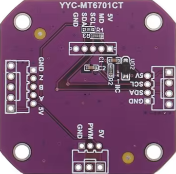
The MT6701 magnetic encoder from MagnTek is a high-precision sensor designed to detect the angular position or rotation of a magnetic field. This component is commonly used in applications requiring accurate position sensing, such as robotics, motor control, and industrial automation.

Explore Projects Built with MT6701 magnetic encoder

Use Cirkit Designer to design, explore, and prototype these projects online. Some projects support real-time simulation. Click "Open Project" to start designing instantly!
Rotary Encoder Interface with STG Adapter for Signal Processing
Image of Encoder in STG: A project utilizing MT6701 magnetic encoder in a practical application
The circuit consists of two rotary encoders (Kalamoyi P3022-V1-CW360) connected to two STG adapters. Each encoder's VCC, OUT, and GND pins are connected to the corresponding STG adapter, facilitating signal transmission and power supply management.
Cirkit Designer LogoOpen Project in Cirkit Designer
Configurable Battery-Powered RF Signal Transmitter with DIP Switch Settings
Image of fyp transmitter: A project utilizing MT6701 magnetic encoder in a practical application
This circuit appears to be a configurable encoder system with an RF transmission capability. The encoder's address pins (A0-A7) are connected to a DIP switch for setting the address, and its data output (DO) is connected to an RF transmitter, allowing the encoded signal to be wirelessly transmitted. The circuit is powered by a 9V battery, regulated to 5V by a 7805 voltage regulator, and includes a diode for polarity protection. Tactile switches are connected to the encoder's data inputs (D1-D3), and an LED with a current-limiting resistor indicates power or activity.
Cirkit Designer LogoOpen Project in Cirkit Designer
Arduino UNO with I2C Multiplexer and Multiple AS5600 Magnetic Encoders
Image of Thesis: A project utilizing MT6701 magnetic encoder in a practical application
This circuit consists of an Arduino UNO microcontroller interfaced with multiple AS5600 magnetic encoders through an Adafruit TCA9548A I2C multiplexer. The encoders are connected to different channels of the multiplexer, allowing the Arduino to communicate with each encoder individually over the I2C bus. The purpose of this circuit is to read multiple rotary positions simultaneously without I2C address conflicts, likely for precision control or feedback in a robotic or automation application.
Cirkit Designer LogoOpen Project in Cirkit Designer
STM32F103C8T6-Based Rotary Encoder with OLED Display
Image of winding: A project utilizing MT6701 magnetic encoder in a practical application
This circuit features an STM32F103C8T6 microcontroller interfaced with an OLED display and a rotary encoder. The microcontroller reads the encoder's phase signals to detect rotational input and communicates with the OLED display via I2C to present information visually.
Cirkit Designer LogoOpen Project in Cirkit Designer

Explore Projects Built with MT6701 magnetic encoder

Use Cirkit Designer to design, explore, and prototype these projects online. Some projects support real-time simulation. Click "Open Project" to start designing instantly!
Image of Encoder in STG: A project utilizing MT6701 magnetic encoder in a practical application
Rotary Encoder Interface with STG Adapter for Signal Processing
The circuit consists of two rotary encoders (Kalamoyi P3022-V1-CW360) connected to two STG adapters. Each encoder's VCC, OUT, and GND pins are connected to the corresponding STG adapter, facilitating signal transmission and power supply management.
Cirkit Designer LogoOpen Project in Cirkit Designer
Image of fyp transmitter: A project utilizing MT6701 magnetic encoder in a practical application
Configurable Battery-Powered RF Signal Transmitter with DIP Switch Settings
This circuit appears to be a configurable encoder system with an RF transmission capability. The encoder's address pins (A0-A7) are connected to a DIP switch for setting the address, and its data output (DO) is connected to an RF transmitter, allowing the encoded signal to be wirelessly transmitted. The circuit is powered by a 9V battery, regulated to 5V by a 7805 voltage regulator, and includes a diode for polarity protection. Tactile switches are connected to the encoder's data inputs (D1-D3), and an LED with a current-limiting resistor indicates power or activity.
Cirkit Designer LogoOpen Project in Cirkit Designer
Image of Thesis: A project utilizing MT6701 magnetic encoder in a practical application
Arduino UNO with I2C Multiplexer and Multiple AS5600 Magnetic Encoders
This circuit consists of an Arduino UNO microcontroller interfaced with multiple AS5600 magnetic encoders through an Adafruit TCA9548A I2C multiplexer. The encoders are connected to different channels of the multiplexer, allowing the Arduino to communicate with each encoder individually over the I2C bus. The purpose of this circuit is to read multiple rotary positions simultaneously without I2C address conflicts, likely for precision control or feedback in a robotic or automation application.
Cirkit Designer LogoOpen Project in Cirkit Designer
Image of winding: A project utilizing MT6701 magnetic encoder in a practical application
STM32F103C8T6-Based Rotary Encoder with OLED Display
This circuit features an STM32F103C8T6 microcontroller interfaced with an OLED display and a rotary encoder. The microcontroller reads the encoder's phase signals to detect rotational input and communicates with the OLED display via I2C to present information visually.
Cirkit Designer LogoOpen Project in Cirkit Designer

Common Applications and Use Cases

  • Rotary position sensing
  • Brushless DC motor commutation
  • Robotics and automation
  • Encoder for industrial control

Technical Specifications

Key Technical Details

  • Supply Voltage (Vcc): 3.3V to 5V
  • Output Voltage (Vo): 0.4V to 2.4V (proportional to magnetic field angle)
  • Operating Temperature Range: -40°C to +125°C
  • Resolution: 12-bit (4096 positions per revolution)
  • Interface: Analog output

Pin Configuration and Descriptions

Pin Number Name Description
1 Vcc Power supply input (3.3V to 5V)
2 GND Ground connection
3 Vo Analog voltage output
4 Vref Reference voltage (optional)

Usage Instructions

How to Use the Component in a Circuit

  1. Power Supply: Connect the Vcc pin to a 3.3V or 5V power supply and the GND pin to the ground.
  2. Output Connection: Connect the Vo pin to an analog input on your microcontroller, such as an Arduino UNO, to read the angular position.
  3. Magnet Placement: Ensure that the magnet is correctly positioned relative to the sensor for accurate readings.

Important Considerations and Best Practices

  • Magnetic Field: Use a diametrically magnetized magnet and align it properly with the sensor.
  • Power Supply: Ensure a stable power supply to avoid fluctuations in readings.
  • Noise Filtering: Implement filtering techniques to minimize electrical noise that can affect the output signal.

Example Code for Arduino UNO

// MT6701 Magnetic Encoder Example Code for Arduino UNO
const int analogPin = A0; // Connect Vo to A0 on Arduino UNO

void setup() {
  Serial.begin(9600); // Start serial communication at 9600 baud rate
}

void loop() {
  int sensorValue = analogRead(analogPin); // Read the analog value from encoder
  float angle = map(sensorValue, 0, 1023, 0, 360); // Map the value to 0-360 degrees
  Serial.print("Angle: ");
  Serial.println(angle); // Print the angle to the Serial Monitor
  delay(100); // Delay for readability
}

Troubleshooting and FAQs

Common Issues Users Might Face

  • Inaccurate Readings: Ensure the magnet is correctly positioned and the power supply is stable.
  • No Output Signal: Check connections to the Vcc and GND pins, and ensure the magnet is present.

Solutions and Tips for Troubleshooting

  • Magnet Position: Adjust the position of the magnet if the readings are inconsistent.
  • Power Supply: Verify that the power supply is within the specified voltage range and is stable.
  • Signal Filtering: Implement low-pass filters to reduce noise in the output signal.

FAQs

Q: Can the MT6701 be used with a 5V system? A: Yes, the MT6701 can operate with a supply voltage between 3.3V and 5V.

Q: What is the resolution of the MT6701? A: The MT6701 has a 12-bit resolution, providing 4096 positions per revolution.

Q: How do I calibrate the MT6701? A: Calibration involves ensuring the magnet is properly aligned and the output voltage is within the expected range for the given angular position.

Q: Is the MT6701 affected by external magnetic fields? A: External magnetic fields can affect the readings. It is recommended to use the MT6701 in an environment with minimal magnetic interference.

For further assistance, please contact MagnTek support or refer to the MT6701 datasheet for more detailed information.