How to Use MAX30102 Heart Rate and Oximeter Sensor V2.0: Examples, Pinouts, and Specs
Introduction
The MAX30102 Heart Rate and Oximeter Sensor V2.0, manufactured by DFRobot, is a compact and highly integrated sensor designed for measuring heart rate and blood oxygen levels. It utilizes photoplethysmography (PPG) technology, which detects changes in blood volume by shining light into the skin and measuring the reflected light. This sensor is ideal for wearable health monitoring devices, fitness trackers, and medical applications.
Explore Projects Built with MAX30102 Heart Rate and Oximeter Sensor V2.0
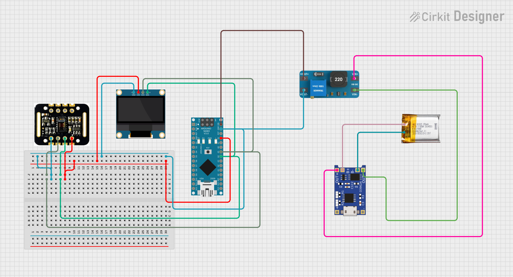
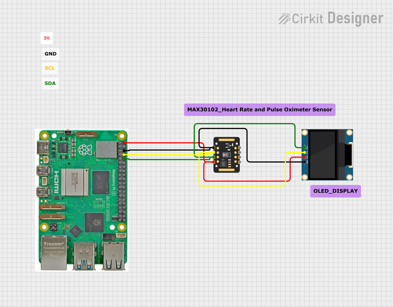
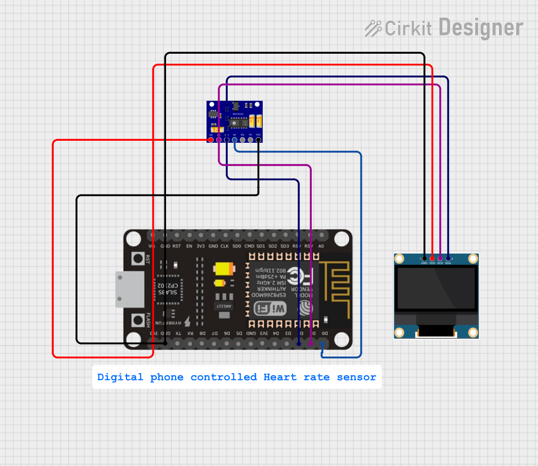
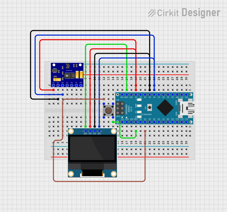
Explore Projects Built with MAX30102 Heart Rate and Oximeter Sensor V2.0
Common Applications and Use Cases
- Wearable health monitoring devices
- Fitness trackers
- Medical-grade pulse oximeters
- Research and development in biomedical engineering
- IoT-based health monitoring systems
Technical Specifications
The MAX30102 sensor is designed for low-power operation and high accuracy. Below are its key technical details:
Key Technical Details
| Parameter | Specification |
|---|---|
| Operating Voltage | 1.8V (internal) and 3.3V (I/O voltage) |
| Operating Current | 600 µA (typical) |
| Standby Current | 0.7 µA |
| Measurement Method | Photoplethysmography (PPG) |
| Communication Interface | I2C |
| Wavelengths | Red: 660 nm, IR: 880 nm |
| Sampling Rate | Programmable (up to 3200 samples/sec) |
| Operating Temperature Range | -40°C to +85°C |
| Dimensions | 13.0 mm x 8.6 mm |
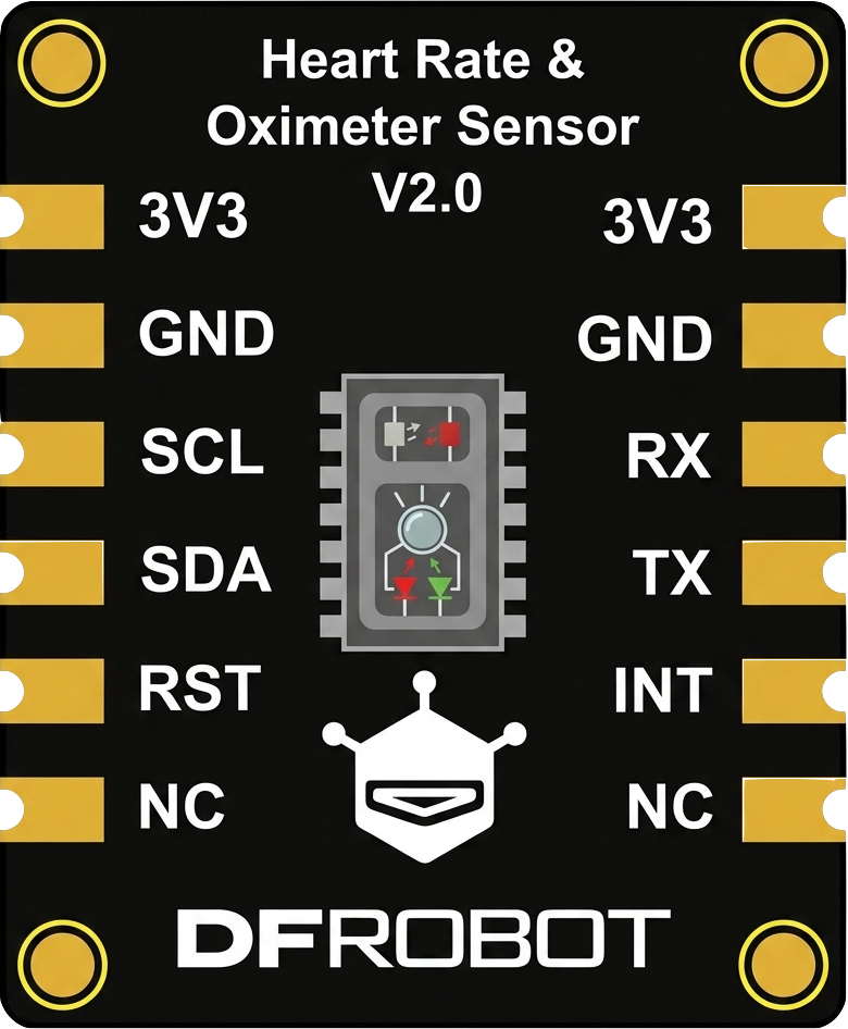
Pin Configuration and Descriptions
The MAX30102 module has the following pinout:
| Pin Name | Pin Type | Description |
|---|---|---|
| VIN | Power | Input voltage (3.3V to 5V) |
| GND | Ground | Ground connection |
| SDA | I2C Data | Serial data line for I2C communication |
| SCL | I2C Clock | Serial clock line for I2C communication |
| INT | Output | Interrupt pin, used to signal data availability or errors (active low) |
Usage Instructions
The MAX30102 sensor is straightforward to use in a circuit, especially with microcontrollers like the Arduino UNO. Below are the steps to integrate and use the sensor:
Connecting the Sensor
- Power Supply: Connect the VIN pin to a 3.3V or 5V power source and the GND pin to ground.
- I2C Communication: Connect the SDA pin to the Arduino's A4 pin (I2C data) and the SCL pin to the A5 pin (I2C clock).
- Interrupt Pin (Optional): Connect the INT pin to a digital input pin on the Arduino if you want to use interrupts.
Arduino Code Example
Below is an example Arduino sketch to read heart rate and SpO2 data from the MAX30102 sensor using the DFRobot MAX30102 library:
#include <Wire.h>
#include "DFRobot_MAX30102.h"

// Create an instance of the MAX30102 sensor
DFRobot_MAX30102 max30102;

void setup() {
  Serial.begin(9600); // Initialize serial communication
  Wire.begin();       // Initialize I2C communication

  // Initialize the MAX30102 sensor
  if (!max30102.begin()) {
    Serial.println("MAX30102 initialization failed. Check connections.");
    while (1); // Halt execution if initialization fails
  }
  Serial.println("MAX30102 initialized successfully.");
}

void loop() {
  // Variables to store heart rate and SpO2 readings
  uint8_t heartRate;
  uint8_t spo2;

  // Read heart rate and SpO2 data
  if (max30102.read(&heartRate, &spo2)) {
    Serial.print("Heart Rate: ");
    Serial.print(heartRate);
    Serial.print(" bpm, SpO2: ");
    Serial.print(spo2);
    Serial.println(" %");
  } else {
    Serial.println("Failed to read data from MAX30102.");
  }

  delay(1000); // Wait 1 second before the next reading
}
Important Considerations and Best Practices
- Power Supply: Ensure the sensor is powered with a stable voltage (3.3V or 5V).
- Ambient Light: Avoid exposing the sensor to excessive ambient light, as it may interfere with measurements.
- Skin Contact: For accurate readings, ensure the sensor is in firm contact with the skin.
- Interrupt Pin: Use the INT pin for efficient data handling in applications requiring real-time processing.
Troubleshooting and FAQs
Common Issues and Solutions
Sensor Not Detected:
- Cause: Incorrect I2C wiring or address mismatch.
- Solution: Verify the SDA and SCL connections and ensure the I2C address matches the library's default (0x57).
Inaccurate Readings:
- Cause: Poor skin contact or excessive ambient light.
- Solution: Ensure the sensor is firmly placed on the skin and shield it from ambient light.
Initialization Fails:
- Cause: Power supply issues or faulty connections.
- Solution: Check the VIN and GND connections and ensure the power supply is stable.
Data Read Errors:
- Cause: I2C communication issues.
- Solution: Check the pull-up resistors on the SDA and SCL lines (typically 4.7kΩ).
FAQs
Q1: Can the MAX30102 measure heart rate through clothing?
A1: No, the sensor requires direct contact with the skin for accurate measurements.
Q2: What is the maximum distance between the sensor and the microcontroller?
A2: The I2C communication protocol typically supports distances up to 1 meter, but shorter distances are recommended for reliable operation.
Q3: Can I use the MAX30102 with a 5V microcontroller?
A3: Yes, the module includes onboard voltage regulation, allowing it to work with 3.3V and 5V systems.
Q4: How do I improve measurement accuracy?
A4: Ensure proper skin contact, minimize motion artifacts, and avoid strong ambient light interference.
By following this documentation, users can effectively integrate and utilize the MAX30102 Heart Rate and Oximeter Sensor V2.0 in their projects.