How to Use LED module 220V 16W(small): Examples, Pinouts, and Specs

Introduction
The LED Module 220V 16W (Small) is a compact and energy-efficient lighting solution designed to operate directly with a 220V AC power supply. With a power consumption of just 16 watts, this module provides bright illumination while maintaining low energy usage. Its small form factor makes it ideal for applications where space is limited, such as in decorative lighting, signage, or compact fixtures.
Explore Projects Built with LED module 220V 16W(small)
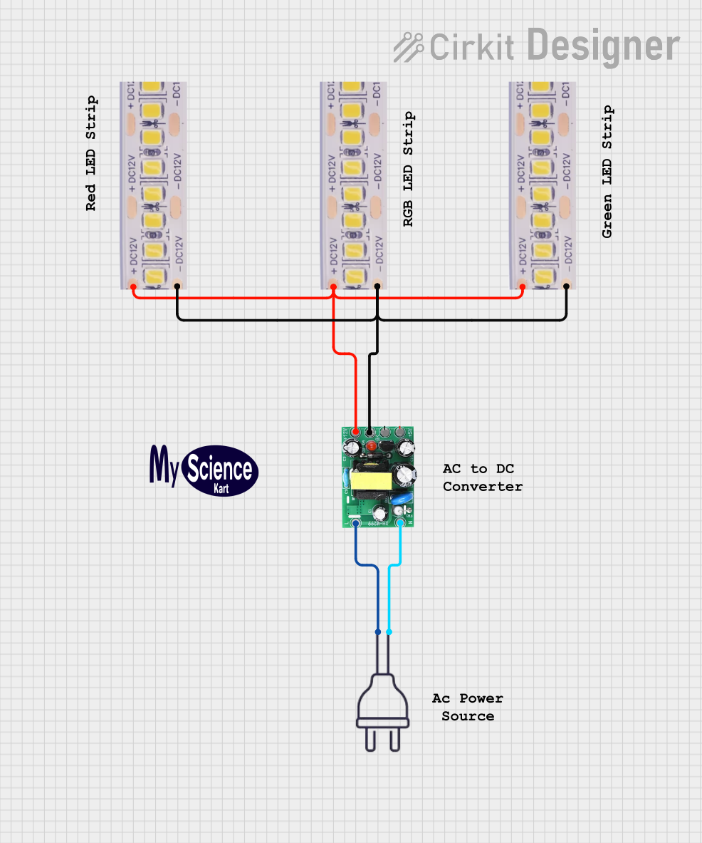


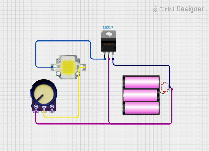
Explore Projects Built with LED module 220V 16W(small)
Common Applications
- Residential and commercial lighting
- Decorative and accent lighting
- Signage and display boards
- Retrofitting traditional lighting systems
- Task lighting in compact spaces
Technical Specifications
Key Specifications
| Parameter | Value |
|---|---|
| Input Voltage | 220V AC |
| Power Consumption | 16W |
| Luminous Efficiency | ~100-120 lumens per watt |
| Color Temperature | 3000K (Warm White) or 6000K (Cool White) |
| Dimensions | Compact (varies by model) |
| Operating Temperature | -20°C to 50°C |
| Lifespan | ~25,000 to 30,000 hours |
| Mounting Type | Screw or adhesive mount |
Pin Configuration and Descriptions
The LED Module 220V 16W (Small) typically has two connection points for AC input. These are not traditional "pins" but rather terminals or solder pads.
| Terminal Name | Description |
|---|---|
| AC Live (L) | Connects to the live wire of the 220V AC supply. |
| AC Neutral (N) | Connects to the neutral wire of the 220V AC supply. |
Note: Ensure proper insulation and secure connections to avoid electrical hazards.
Usage Instructions
How to Use the LED Module in a Circuit
Power Supply Connection:
- Connect the AC Live (L) terminal of the module to the live wire of the 220V AC power supply.
- Connect the AC Neutral (N) terminal to the neutral wire of the power supply.
- Use insulated wires and ensure all connections are secure to prevent short circuits.
Mounting:
- Secure the module using screws or adhesive backing, depending on the design.
- Ensure the module is mounted on a heat-dissipating surface to prevent overheating.
Safety Precautions:
- Always disconnect the power supply before handling or installing the module.
- Avoid direct contact with the module when powered, as it operates at high voltage.
Important Considerations
- Heat Management: Ensure adequate ventilation or heat sinking to maintain optimal performance and lifespan.
- Polarity: While the module operates on AC, ensure correct wiring to avoid damage.
- Environment: Avoid exposure to moisture or extreme temperatures unless the module is rated for such conditions.
Arduino Compatibility
This module is not directly compatible with Arduino or other microcontrollers due to its high voltage (220V AC) operation. However, it can be controlled indirectly using a relay module or a solid-state relay (SSR). Below is an example of how to control the LED module using an Arduino and a relay.
Example Code for Arduino with Relay
/*
  This code demonstrates how to control a 220V LED module using a relay.
  WARNING: High voltage is involved. Ensure proper insulation and safety measures.
  Do not handle the circuit while powered.
*/

const int relayPin = 7; // Pin connected to the relay module

void setup() {
  pinMode(relayPin, OUTPUT); // Set the relay pin as an output
  digitalWrite(relayPin, LOW); // Ensure the relay is off initially
}

void loop() {
  digitalWrite(relayPin, HIGH); // Turn on the LED module
  delay(5000); // Keep it on for 5 seconds
  digitalWrite(relayPin, LOW); // Turn off the LED module
  delay(5000); // Keep it off for 5 seconds
}
Note: Use a relay module rated for 220V AC and ensure proper isolation between the Arduino and the high-voltage circuit.
Troubleshooting and FAQs
Common Issues and Solutions
| Issue | Possible Cause | Solution |
|---|---|---|
| LED module does not light up | Loose or incorrect wiring | Check and secure all connections. |
| Flickering light | Unstable power supply or poor connection | Use a stable power source and check wiring. |
| Overheating | Inadequate heat dissipation | Mount on a heat sink or ventilated surface. |
| Reduced brightness over time | Aging or overheating of LEDs | Ensure proper cooling and replace if necessary. |
FAQs
Can I dim the LED module?
- This module is not inherently dimmable. Use a compatible dimmer circuit or module if dimming is required.
Is the module waterproof?
- Unless specified as waterproof, avoid using the module in wet or humid environments.
Can I use this module with a 110V AC supply?
- No, this module is designed specifically for 220V AC operation.
What precautions should I take during installation?
- Always disconnect the power supply before installation, and ensure proper insulation and secure connections to prevent electrical hazards.
By following this documentation, you can safely and effectively use the LED Module 220V 16W (Small) in your projects.