
How to Use SparkFun FTDI Basic Breakout (5V): Examples, Pinouts, and Specs
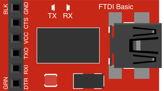
 Design with SparkFun FTDI Basic Breakout (5V) in Cirkit Designer
Introduction
The SparkFun FTDI Basic Breakout (5V) (Manufacturer Part ID: DEV-09716) is a USB-to-serial converter designed to facilitate seamless communication between a computer and microcontrollers or other serial devices. Operating at 5V, this compact and reliable module is widely used for programming, debugging, and serial communication tasks. It is particularly popular for interfacing with Arduino boards and other development platforms that require USB-to-serial conversion.
Explore Projects Built with SparkFun FTDI Basic Breakout (5V)
 Open Project in Cirkit Designer
 Open Project in Cirkit Designer
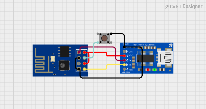 Open Project in Cirkit Designer
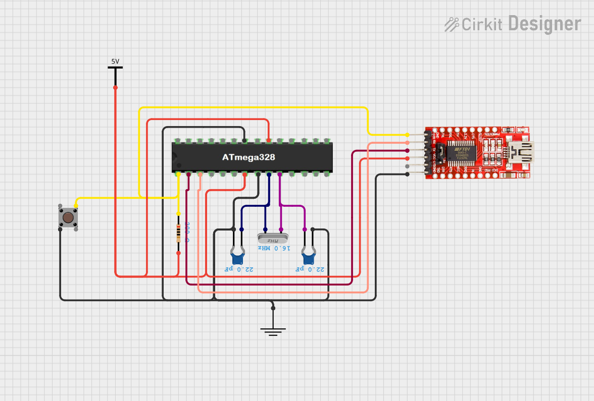 Open Project in Cirkit Designer
Explore Projects Built with SparkFun FTDI Basic Breakout (5V)
Open Project in Cirkit DesignerOpen Project in Cirkit DesignerOpen Project in Cirkit DesignerOpen Project in Cirkit DesignerCommon Applications and Use Cases
- Programming Arduino Pro, Pro Mini, and other microcontroller boards.
- Debugging and monitoring serial data from embedded systems.
- Interfacing with serial devices such as GPS modules, sensors, and displays.
- USB-to-TTL communication for custom electronics projects.
Technical Specifications
The following table outlines the key technical details of the SparkFun FTDI Basic Breakout (5V):
| Parameter | Specification |
|---|---|
| Operating Voltage | 5V |
| USB Interface | USB Mini-B |
| Serial Communication | TTL-level (5V logic) |
| Chipset | FTDI FT232RL |
| Data Rate | Up to 3 Mbps |
| Pin Header Pitch | 0.1 inch (2.54 mm) |
| Dimensions | 1.3" x 0.6" (33 mm x 15 mm) |
| Mounting Style | Through-hole |
Pin Configuration and Descriptions
The SparkFun FTDI Basic Breakout (5V) features a 6-pin header for serial communication. The pinout is as follows:
| Pin | Label | Description |
|---|---|---|
| 1 | DTR | Data Terminal Ready - Used for resetting microcontrollers during programming. |
| 2 | RXI | Receive Data - Serial data received from the microcontroller or device. |
| 3 | TXO | Transmit Data - Serial data sent to the microcontroller or device. |
| 4 | VCC | 5V Power Output - Supplies power to the connected device. |
| 5 | CTS | Clear to Send - Flow control signal (optional, often unused). |
| 6 | GND | Ground - Common ground connection. |
Usage Instructions
How to Use the Component in a Circuit
Connect the FTDI Basic Breakout to Your Computer:
- Use a USB Mini-B cable to connect the breakout board to your computer. Ensure the drivers for the FTDI FT232RL chip are installed (available on the SparkFun website or FTDI's official site).
Connect to a Microcontroller or Serial Device:
- Align the 6-pin header of the FTDI Basic Breakout with the corresponding pins on your microcontroller or device. Ensure the pin labels (DTR, RXI, TXO, etc.) match.
Power the Device:
- The breakout board provides a 5V output (VCC pin) to power the connected device. Ensure the device operates at 5V logic levels.
Program or Communicate:
- Use a serial terminal program (e.g., Arduino IDE Serial Monitor, PuTTY) or programming software to send and receive data.
Important Considerations and Best Practices
- Voltage Compatibility: Ensure the connected device operates at 5V logic levels. For 3.3V devices, use a level shifter or the 3.3V version of the FTDI Basic Breakout.
- DTR Pin: The DTR pin is used to reset Arduino boards during programming. Ensure it is connected to the reset pin of the microcontroller.
- Driver Installation: Install the appropriate FTDI drivers before use. Without the drivers, the breakout board may not be recognized by your computer.
- Avoid Overloading: Do not exceed the current rating of the VCC pin when powering external devices.
Example: Using with Arduino UNO
Although the FTDI Basic Breakout is commonly used with Arduino Pro or Pro Mini, it can also be used for serial communication with an Arduino UNO. Below is an example Arduino sketch and serial communication code:
Arduino Sketch
// Example Arduino sketch for serial communication with FTDI Basic Breakout
void setup() {
  Serial.begin(9600); // Initialize serial communication at 9600 baud
  Serial.println("FTDI Basic Breakout Test"); // Send a test message
}

void loop() {
  if (Serial.available() > 0) { // Check if data is available to read
    char received = Serial.read(); // Read the incoming byte
    Serial.print("Received: ");
    Serial.println(received); // Echo the received byte back to the sender
  }
}
Serial Communication via FTDI
- Upload the sketch to your Arduino UNO.
- Disconnect the Arduino UNO from your computer.
- Connect the FTDI Basic Breakout to the Arduino UNO's RX, TX, and GND pins.
- Open a serial terminal program and communicate with the Arduino UNO via the FTDI Basic Breakout.
Troubleshooting and FAQs
Common Issues and Solutions
FTDI Breakout Not Recognized by Computer:
- Ensure the FTDI drivers are installed correctly.
- Try a different USB cable or port.
- Check the device manager (Windows) or system profiler (Mac) for the FTDI device.
No Serial Communication:
- Verify the RX and TX connections. RX on the FTDI should connect to TX on the device, and vice versa.
- Ensure the baud rate in the serial terminal matches the baud rate in your code.
Device Not Powering On:
- Check the VCC and GND connections.
- Ensure the connected device does not draw more current than the FTDI breakout can supply.
Programming Fails on Arduino Pro/Pro Mini:
- Ensure the DTR pin is connected to the reset pin of the Arduino.
- Verify the correct board and port are selected in the Arduino IDE.
FAQs
Q: Can I use this breakout board with 3.3V devices?
A: No, this version operates at 5V logic levels. Use the 3.3V version of the FTDI Basic Breakout for 3.3V devices.
Q: What is the maximum current output of the VCC pin?
A: The VCC pin can supply up to 500 mA, depending on the USB port's capability.
Q: Do I need to install drivers for macOS or Linux?
A: macOS and most Linux distributions include built-in support for FTDI devices. However, you may need to install drivers for older systems.
Q: Can I use this breakout board for debugging?
A: Yes, the FTDI Basic Breakout is ideal for debugging serial communication in embedded systems.