How to Use ESP32 Relay X2: Examples, Pinouts, and Specs
Introduction
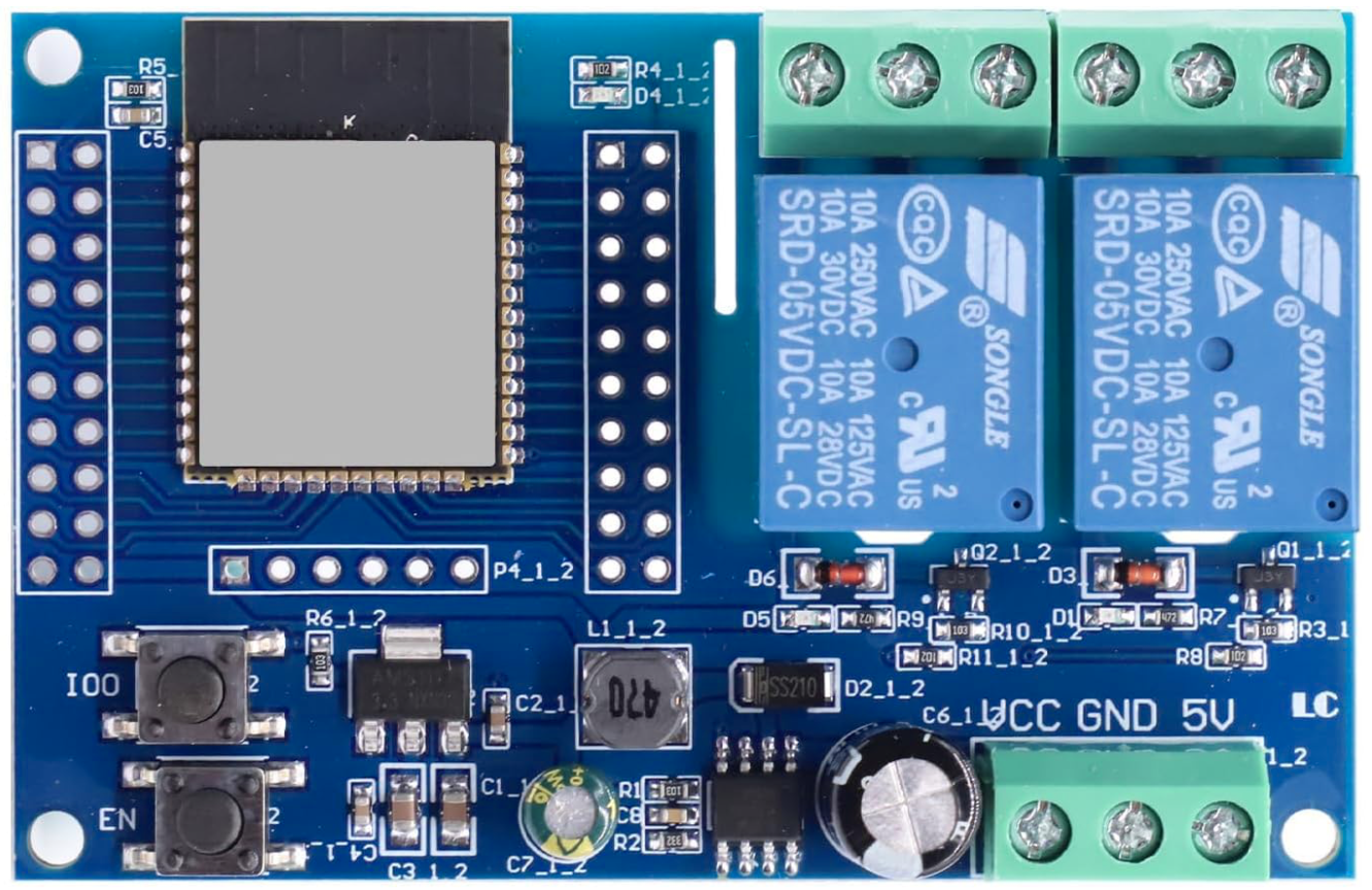
The ESP32 Relay X2 is a dual-channel relay module designed to interface seamlessly with the ESP32 microcontroller. It allows users to control high-voltage devices such as lights, fans, or appliances using low-voltage digital signals. Each relay channel can be independently controlled, making it ideal for home automation, IoT projects, and industrial control systems.
Explore Projects Built with ESP32 Relay X2


Explore Projects Built with ESP32 Relay X2
Common Applications and Use Cases
- Home automation (e.g., controlling lights, fans, or appliances)
- IoT projects requiring high-voltage device control
- Industrial automation and control systems
- Smart energy management systems
- Prototyping and educational projects
Technical Specifications
The following table outlines the key technical details of the ESP32 Relay X2 module:
| Parameter | Specification |
|---|---|
| Operating Voltage | 5V DC |
| Control Signal Voltage | 3.3V (compatible with ESP32 logic levels) |
| Relay Channels | 2 |
| Maximum Load Voltage | 250V AC / 30V DC |
| Maximum Load Current | 10A per channel |
| Trigger Type | Active Low |
| Dimensions | 50mm x 40mm x 20mm |
Pin Configuration and Descriptions
The ESP32 Relay X2 module has the following pinout:
Input Pins (Control Side)
| Pin Name | Description |
|---|---|
| VCC | 5V power supply input for the relay module |
| GND | Ground connection |
| IN1 | Control signal for Relay 1 (Active Low) |
| IN2 | Control signal for Relay 2 (Active Low) |
Output Pins (Relay Side)
Each relay channel has three output terminals:
| Terminal | Description |
|---|---|
| COM | Common terminal |
| NO | Normally Open terminal (connected to COM when active) |
| NC | Normally Closed terminal (connected to COM when idle) |
Usage Instructions
How to Use the ESP32 Relay X2 in a Circuit
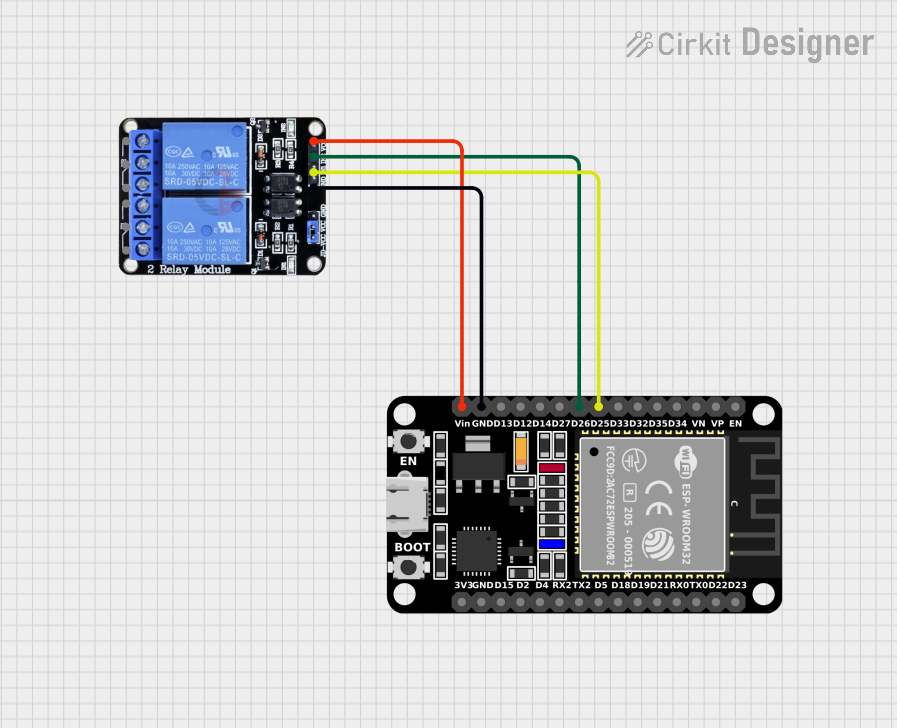
- Power the Module: Connect the VCC pin to a 5V power source and the GND pin to ground.
- Connect the ESP32:
- Connect the IN1 pin to a GPIO pin on the ESP32 to control Relay 1.
- Connect the IN2 pin to another GPIO pin on the ESP32 to control Relay 2.
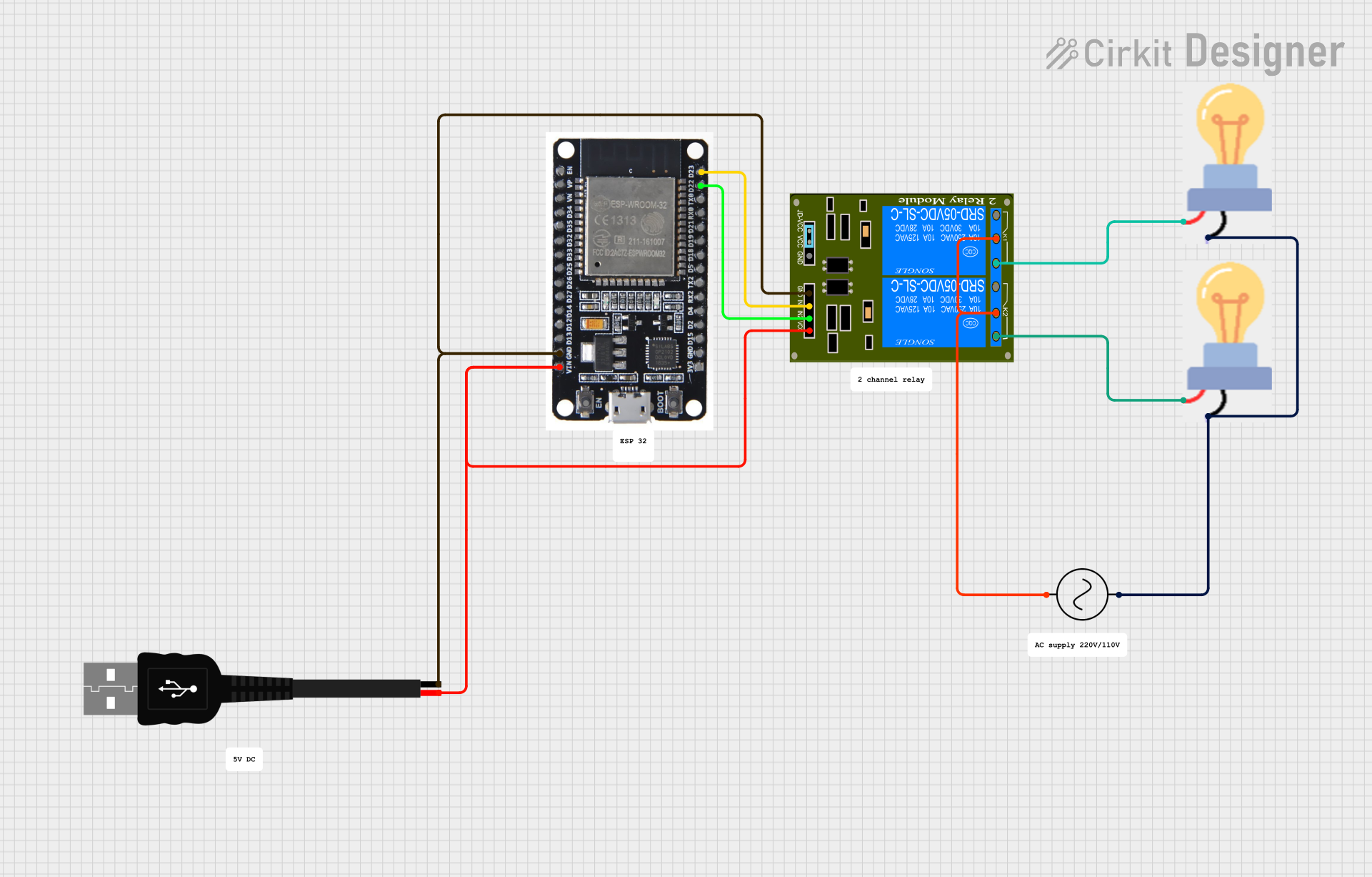
- Connect the Load:
- For each relay, connect the high-voltage device to the COM and NO terminals if you want the device to turn on when the relay is active.
- Use the COM and NC terminals if you want the device to turn off when the relay is active.
- Control the Relays: Use the ESP32 to send LOW signals to the IN1 or IN2 pins to activate the corresponding relay.
Important Considerations and Best Practices
- Power Supply: Ensure the module is powered with a stable 5V DC supply. Do not exceed the voltage rating.
- Isolation: The relay module provides electrical isolation between the control and load sides. However, always exercise caution when working with high-voltage circuits.
- Load Ratings: Do not exceed the maximum load voltage (250V AC / 30V DC) or current (10A) for each relay channel.
- GPIO Pin Configuration: Configure the ESP32 GPIO pins as outputs in your code to control the relays.
Example Code for ESP32
Below is an example Arduino sketch to control the ESP32 Relay X2 module:
// Define GPIO pins for the relay control signals
#define RELAY1_PIN  26  // GPIO pin connected to IN1
#define RELAY2_PIN  27  // GPIO pin connected to IN2

void setup() {
  // Initialize serial communication for debugging
  Serial.begin(115200);

  // Set relay pins as outputs
  pinMode(RELAY1_PIN, OUTPUT);
  pinMode(RELAY2_PIN, OUTPUT);

  // Ensure relays are off at startup
  digitalWrite(RELAY1_PIN, HIGH); // Relay is active low
  digitalWrite(RELAY2_PIN, HIGH); // Relay is active low
}

void loop() {
  // Turn on Relay 1
  Serial.println("Turning on Relay 1");
  digitalWrite(RELAY1_PIN, LOW); // Activate relay
  delay(2000); // Wait for 2 seconds

  // Turn off Relay 1
  Serial.println("Turning off Relay 1");
  digitalWrite(RELAY1_PIN, HIGH); // Deactivate relay
  delay(2000); // Wait for 2 seconds

  // Turn on Relay 2
  Serial.println("Turning on Relay 2");
  digitalWrite(RELAY2_PIN, LOW); // Activate relay
  delay(2000); // Wait for 2 seconds

  // Turn off Relay 2
  Serial.println("Turning off Relay 2");
  digitalWrite(RELAY2_PIN, HIGH); // Deactivate relay
  delay(2000); // Wait for 2 seconds
}
Troubleshooting and FAQs
Common Issues and Solutions
Relays Not Activating:
- Ensure the VCC and GND pins are properly connected to a 5V power source.
- Verify that the control signals (IN1 and IN2) are being driven LOW by the ESP32.
ESP32 GPIO Pins Not Working:
- Check that the GPIO pins used for IN1 and IN2 are configured as outputs in your code.
- Avoid using GPIO pins that are reserved for special functions on the ESP32 (e.g., GPIO0, GPIO2).
Load Not Switching:
- Confirm that the load is properly connected to the relay terminals (COM, NO, or NC).
- Ensure the load does not exceed the relay's voltage or current ratings.
Relay Module Overheating:
- Check that the load current does not exceed 10A per channel.
- Use proper heat dissipation techniques if the module is used for extended periods.
FAQs
Q1: Can I use the ESP32 Relay X2 with a 3.3V power supply?
A1: No, the module requires a 5V power supply for proper operation. However, the control signals are compatible with the ESP32's 3.3V logic levels.
Q2: Is the relay module opto-isolated?
A2: No, the ESP32 Relay X2 does not include opto-isolation. For additional safety, consider using an opto-isolated relay module.
Q3: Can I control both relays simultaneously?
A3: Yes, you can control both relays independently or simultaneously by sending appropriate signals to the IN1 and IN2 pins.
Q4: What happens if I send a HIGH signal to the IN1 or IN2 pins?
A4: The corresponding relay will deactivate, and the load connected to the NO terminal will turn off.