How to Use Digispark ATTINY85: Examples, Pinouts, and Specs
Introduction
The Digispark ATTINY85 is a compact, low-cost microcontroller development board manufactured by Digistump. It is based on the ATtiny85 microcontroller chip and is designed for rapid prototyping and development of small-scale electronic projects. The board is compatible with the Arduino IDE, making it accessible to both beginners and experienced developers.
Explore Projects Built with Digispark ATTINY85
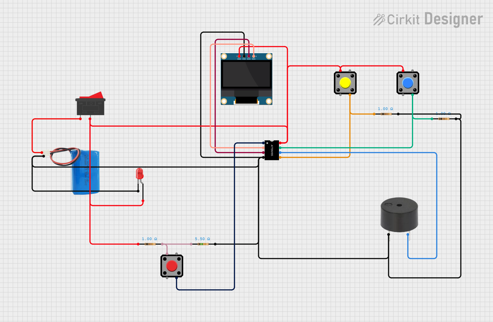


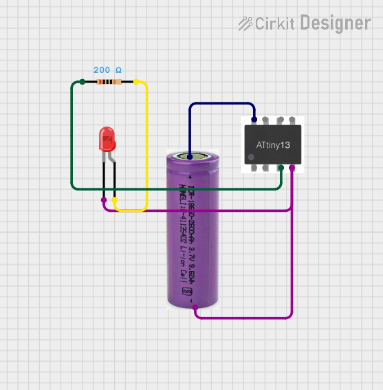
Explore Projects Built with Digispark ATTINY85
Common Applications and Use Cases
- IoT (Internet of Things) devices
- Wearable electronics
- LED control and lighting projects
- Sensor-based systems
- USB peripherals and HID (Human Interface Device) emulation
- Small robotics and automation projects
Technical Specifications
The Digispark ATTINY85 is a versatile board with the following key specifications:
| Specification | Details |
|---|---|
| Microcontroller | ATtiny85 |
| Operating Voltage | 5V |
| Input Voltage (USB) | 5V |
| Flash Memory | 8 KB (6 KB available for user code after bootloader) |
| SRAM | 512 bytes |
| EEPROM | 512 bytes |
| Clock Speed | 16.5 MHz (internal oscillator) |
| Digital I/O Pins | 6 (all can be used as PWM outputs) |
| Analog Input Pins | 3 |
| USB Support | Built-in USB interface for programming and communication |
| Dimensions | 25 mm x 18 mm |
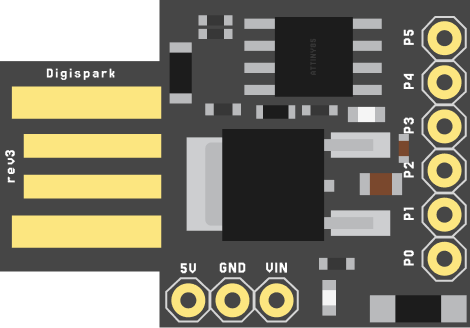
Pin Configuration and Descriptions
The Digispark ATTINY85 has 6 I/O pins, which are multifunctional and can be used for digital, analog, or PWM operations. Below is the pinout description:
| Pin | Name | Function |
|---|---|---|
| P0 | D0 | Digital I/O, PWM, USB+ (used during USB communication) |
| P1 | D1 | Digital I/O, PWM, USB- (used during USB communication) |
| P2 | D2 | Digital I/O, PWM, Analog Input (A1) |
| P3 | D3 | Digital I/O, PWM, Analog Input (A3), I²C SDA |
| P4 | D4 | Digital I/O, PWM, Analog Input (A2), I²C SCL |
| P5 | D5 | Digital I/O, PWM, Reset (active low, used for programming) |
Usage Instructions
How to Use the Digispark ATTINY85 in a Circuit
- Install the Arduino IDE: Ensure you have the Arduino IDE installed on your computer.
- Add Digispark Board Support:
- Open the Arduino IDE.
- Go to
File > Preferences. - In the "Additional Board Manager URLs" field, add the following URL:
http://digistump.com/package_digistump_index.json - Go to
Tools > Board > Boards Manager, search for "Digistump AVR Boards," and install it.
- Connect the Digispark:
- Plug the Digispark ATTINY85 directly into a USB port on your computer.
- No external USB cable is required.
- Write and Upload Code:
- Select
Tools > Board > Digispark (Default - 16.5 MHz)in the Arduino IDE. - Write your code in the IDE.
- Click the "Upload" button. When prompted, unplug and replug the Digispark to initiate the upload process.
- Select
Example Code: Blinking an LED
The following example demonstrates how to blink an LED connected to pin P0 (D0):
// Blink an LED on Digispark ATTINY85
// Connect the positive leg of the LED to P0 (D0) and the negative leg to GND.

void setup() {
  pinMode(0, OUTPUT); // Set pin P0 (D0) as an output
}

void loop() {
  digitalWrite(0, HIGH); // Turn the LED on
  delay(1000);           // Wait for 1 second
  digitalWrite(0, LOW);  // Turn the LED off
  delay(1000);           // Wait for 1 second
}
Important Considerations and Best Practices
- USB Communication: Pins P0 and P1 are used for USB communication. Avoid using these pins for other purposes when USB is active.
- Power Supply: The Digispark is powered directly via USB. Ensure your USB port can supply sufficient current for your project.
- Reset Pin (P5): Pin P5 doubles as the reset pin. Be cautious when using it in your circuit, as it may interfere with programming.
- Limited Resources: The ATtiny85 has limited memory and processing power. Optimize your code to fit within the constraints.
Troubleshooting and FAQs
Common Issues and Solutions
Problem: The Digispark is not recognized by the computer.
Solution: Ensure the necessary drivers are installed. Visit the Digistump website to download and install the drivers for your operating system.Problem: Code upload fails or times out.
Solution: Unplug the Digispark, click "Upload" in the Arduino IDE, and replug the board when prompted.Problem: USB communication is unstable.
Solution: Avoid using P0 and P1 for other purposes while USB communication is active. Ensure the USB port provides stable power.Problem: The board does not power on.
Solution: Check the USB connection and ensure the port is functional. Try a different USB port if necessary.
FAQs
Can I use the Digispark with external power?
Yes, you can power the board with an external 5V source by connecting it to the VCC and GND pins.Is the Digispark compatible with all Arduino libraries?
Not all libraries are compatible due to the limited memory and processing power of the ATtiny85. Use lightweight libraries whenever possible.How do I reset the Digispark?
The Digispark resets automatically when replugged into the USB port. Alternatively, you can manually reset it by pulling the P5 (Reset) pin low.
This documentation provides a comprehensive guide to using the Digispark ATTINY85 for your projects. With its small size and ease of use, the Digispark is an excellent choice for compact and cost-effective designs.