How to Use 3.3V Step-Up Voltage Regulator : Examples, Pinouts, and Specs
Pololu 3.3V Step-Up Voltage Regulator (u1v11f3) Documentation
1. Introduction
The Pololu 3.3V Step-Up Voltage Regulator (part ID: u1v11f3) is a compact and efficient DC-DC boost converter designed to increase a lower input voltage to a stable 3.3V output. This regulator is ideal for powering low-voltage devices that require a consistent 3.3V supply, even when the input voltage is below 3.3V. It is particularly useful in battery-powered applications, where the input voltage may vary or drop over time.
Common Applications
- Powering 3.3V microcontrollers (e.g., ESP8266, ESP32) from lower voltage sources.
- Extending the usable life of batteries by boosting their voltage.
- Supplying 3.3V to sensors, modules, and other low-power devices.
- Portable electronics and wearables.
- Robotics and IoT devices.
2. Technical Specifications
The following table outlines the key technical details of the Pololu u1v11f3 regulator:
| Parameter | Value |
|---|---|
| Input Voltage Range | 0.5V to 5.5V |
| Output Voltage | 3.3V (fixed) |
| Maximum Output Current | Up to 200 mA (depending on input voltage; see notes below) |
| Efficiency | Up to 90% (varies with input voltage and load) |
| Quiescent Current | 20 µA (typical, with no load) |
| Dimensions | 11.4 mm × 8.9 mm × 3.0 mm |
| Weight | 0.3 g |
| Operating Temperature Range | -40°C to +85°C |
| Protection Features | None (no reverse polarity or overcurrent protection; external protection recommended) |
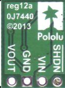
Pin Configuration and Descriptions
The Pololu u1v11f3 regulator has three pins, as described in the table below:
| Pin Name | Pin Type | Description |
|---|---|---|
| VIN | Input | Connect to the input voltage source (0.5V to 5.5V). |
| GND | Ground | Connect to the ground of the circuit. |
| VOUT | Output | Provides a stable 3.3V output. Connect to the load requiring 3.3V. |
3. Usage Instructions
Connecting the Regulator in a Circuit
- Input Voltage Source: Connect the VIN pin to a power source (e.g., a single AA/AAA battery, a 3.7V LiPo battery, or a low-voltage power supply). Ensure the input voltage is within the range of 0.5V to 5.5V.
- Ground Connection: Connect the GND pin to the ground of your circuit.
- Output Voltage: Connect the VOUT pin to the device or circuit requiring a 3.3V supply.
Important Considerations
- Input Voltage Range: Ensure the input voltage does not exceed 5.5V, as this may damage the regulator.
- Output Current Limitations: The maximum output current depends on the input voltage. For example:
- At 1.2V input, the regulator can supply up to 100 mA.
- At 3.0V input, the regulator can supply up to 200 mA.
- Heat Dissipation: While the regulator is efficient, excessive current draw may cause it to heat up. Ensure proper ventilation or heat dissipation if operating near the maximum current limit.
- External Protection: The regulator does not include built-in reverse polarity or overcurrent protection. Use external diodes or fuses for added safety.
4. Example Application with Arduino UNO
The Pololu 3.3V Step-Up Voltage Regulator can be used to power 3.3V sensors or modules in an Arduino-based project. Below is an example of using the regulator to power a 3.3V temperature sensor (e.g., DHT11) connected to an Arduino UNO.
Wiring Diagram
- Connect the VIN pin of the regulator to a 1.5V AA battery.
- Connect the GND pin of the regulator to the ground of the battery and the Arduino UNO.
- Connect the VOUT pin of the regulator to the VCC pin of the DHT11 sensor.
- Connect the data pin of the DHT11 sensor to a digital pin on the Arduino UNO (e.g., pin 2).
Arduino Code Example
#include <DHT.h>

// Define the DHT sensor type and pin
#define DHTPIN 2       // Data pin connected to DHT11
#define DHTTYPE DHT11  // DHT11 sensor type

DHT dht(DHTPIN, DHTTYPE);

void setup() {
  Serial.begin(9600);  // Initialize serial communication
  dht.begin();         // Initialize the DHT sensor
  Serial.println("DHT11 Sensor Test");
}

void loop() {
  delay(2000);  // Wait 2 seconds between readings

  // Read temperature and humidity from the DHT11 sensor
  float humidity = dht.readHumidity();
  float temperature = dht.readTemperature();

  // Check if the readings are valid
  if (isnan(humidity) || isnan(temperature)) {
    Serial.println("Failed to read from DHT sensor!");
    return;
  }

  // Print the readings to the Serial Monitor
  Serial.print("Humidity: ");
  Serial.print(humidity);
  Serial.print("%  Temperature: ");
  Serial.print(temperature);
  Serial.println("°C");
}
Notes
- The regulator ensures a stable 3.3V supply to the DHT11 sensor, even if the input voltage from the battery drops below 3.3V.
- Ensure the total current draw of the Arduino and connected devices does not exceed the regulator's output current limit.
5. Troubleshooting and FAQs
Common Issues and Solutions
| Issue | Possible Cause | Solution |
|---|---|---|
| No output voltage | Incorrect wiring or input voltage out of range | Verify connections and ensure input voltage is between 0.5V and 5.5V. |
| Output voltage is unstable or noisy | Excessive load current or insufficient input voltage | Reduce the load or increase the input voltage. Add a capacitor across VOUT. |
| Regulator overheating | Output current exceeds the regulator's capacity | Reduce the load current or improve heat dissipation. |
| Device connected to VOUT is not working | Voltage drop due to high current draw or poor connections | Check wiring and ensure the load does not exceed the regulator's capabilities. |
FAQs
Can I use this regulator to power a 3.3V microcontroller?
- Yes, as long as the microcontroller's current requirements are within the regulator's output current limit.
What happens if the input voltage exceeds 5.5V?
- The regulator may be permanently damaged. Use a voltage limiter or zener diode to protect the input.
Can I use this regulator with a rechargeable battery?
- Yes, it works well with rechargeable batteries like NiMH or LiPo, as long as the input voltage is within range.
Does the regulator have reverse polarity protection?
- No, it does not. Use an external diode to protect against reverse polarity.
This documentation provides a comprehensive guide to using the Pololu 3.3V Step-Up Voltage Regulator (u1v11f3). By following the instructions and best practices outlined above, you can ensure reliable and efficient operation in your projects.
Explore Projects Built with 3.3V Step-Up Voltage Regulator


Explore Projects Built with 3.3V Step-Up Voltage Regulator