How to Use 10-Channel Light/Color Sensor: Examples, Pinouts, and Specs
Introduction
The Adafruit AS7341 is a highly advanced 10-channel light and color sensor designed for precise spectral analysis. It can measure light intensity and color across ten distinct channels, making it ideal for applications requiring detailed environmental light analysis or color recognition. The sensor is compact, efficient, and communicates via the I2C interface, making it easy to integrate into a wide range of projects.
Explore Projects Built with 10-Channel Light/Color Sensor
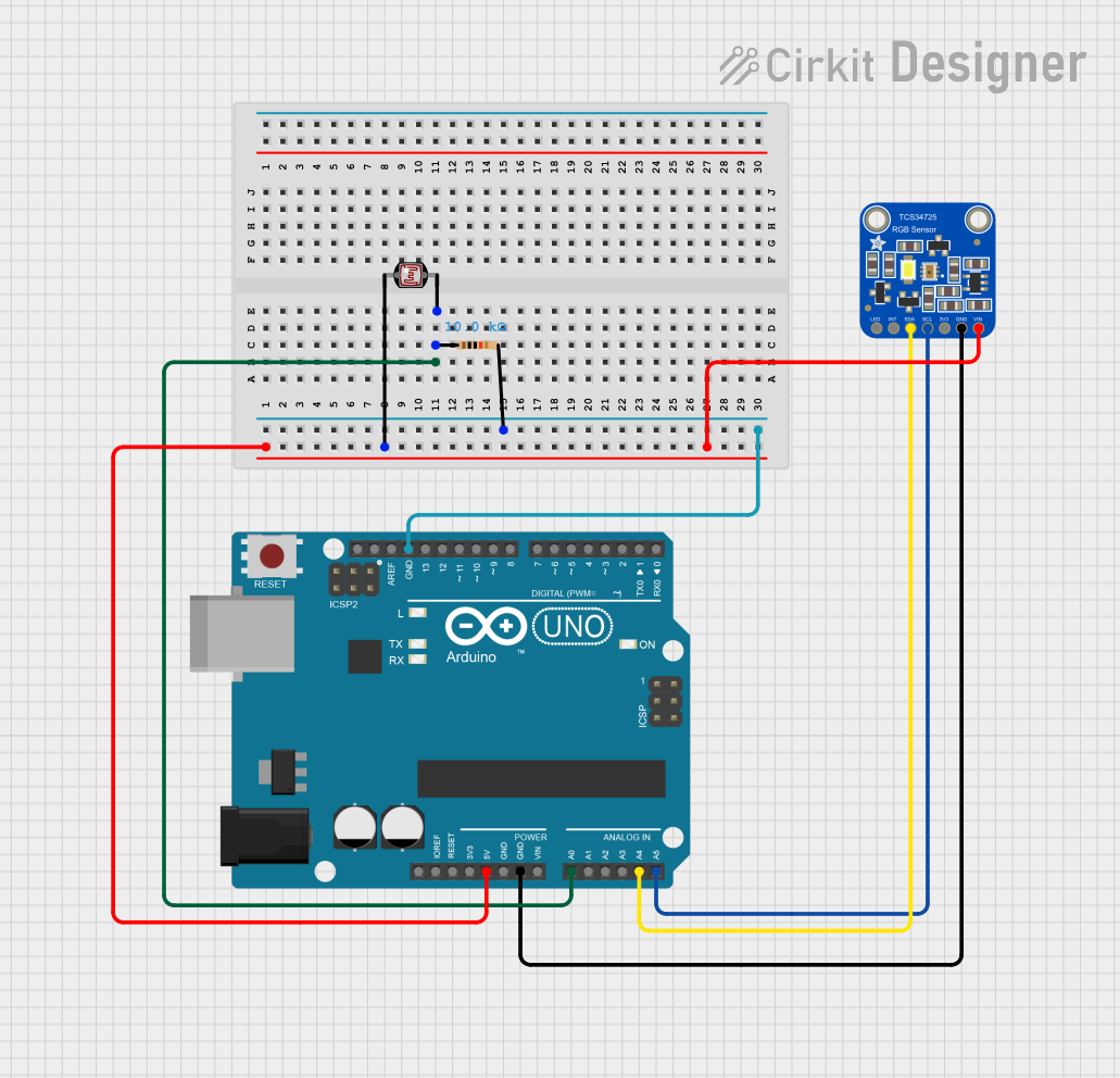
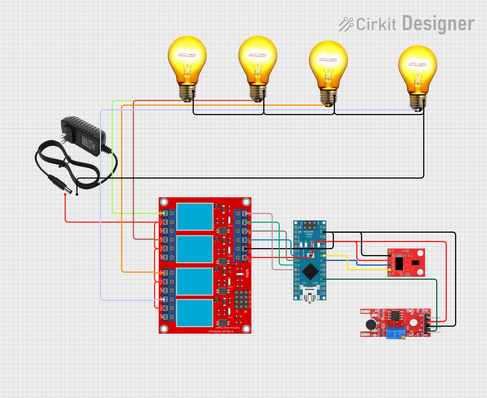

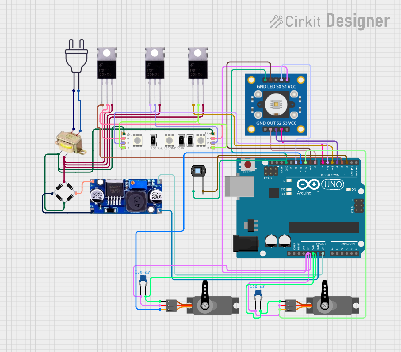
Explore Projects Built with 10-Channel Light/Color Sensor
Common Applications and Use Cases
- Ambient light sensing for smart lighting systems
- Color matching and calibration in industrial applications
- Environmental monitoring and spectral analysis
- Agricultural applications, such as plant health monitoring
- Consumer electronics, including displays and cameras
- Scientific research and educational projects
Technical Specifications
The AS7341 sensor is packed with features that make it versatile and powerful. Below are its key technical specifications:
| Parameter | Value |
|---|---|
| Manufacturer | Adafruit |
| Part ID | AS7341 |
| Operating Voltage | 3.3V (logic level) |
| Supply Voltage Range | 2.7V to 3.6V |
| Communication Interface | I2C (7-bit address: 0x39) |
| Spectral Channels | 10 (visible and near-infrared) |
| Spectral Range | 415 nm to 940 nm |
| Measurement Modes | Flicker detection, spectral sensing |
| Operating Temperature | -40°C to +85°C |
| Dimensions | 20mm x 17mm x 2mm |
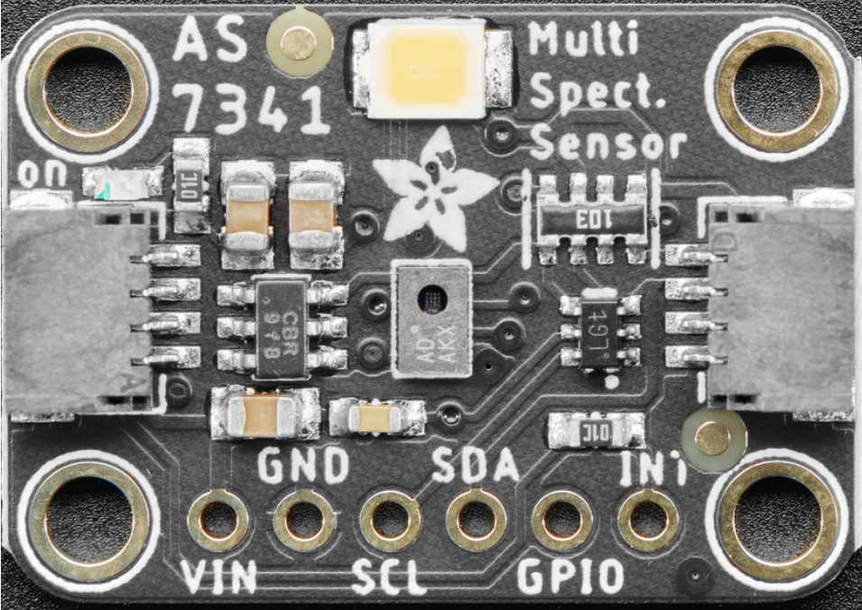
Pin Configuration and Descriptions
The AS7341 sensor breakout board has the following pin layout:
| Pin Name | Description |
|---|---|
| VIN | Power supply input (3.3V or 5V) |
| GND | Ground |
| SCL | I2C clock line |
| SDA | I2C data line |
| INT | Interrupt pin (optional, for event notifications) |
| LDR | LED driver pin (optional, for external light source) |
| RST | Reset pin (optional, active low) |
Usage Instructions
The AS7341 sensor is straightforward to use, especially with the Adafruit library for Arduino. Below are the steps to get started:
Connecting the Sensor
- Power the Sensor: Connect the VIN pin to a 3.3V or 5V power source and the GND pin to ground.
- I2C Communication: Connect the SCL pin to the Arduino's SCL pin and the SDA pin to the Arduino's SDA pin.
- Optional Connections:
- Connect the INT pin to a digital input pin on the Arduino if you want to use interrupts.
- Use the LDR pin to control an external light source if needed.
Arduino Code Example
Below is an example of how to use the AS7341 sensor with an Arduino UNO. This code reads the spectral data and prints it to the Serial Monitor.
#include <Wire.h>
#include "Adafruit_AS7341.h"

// Create an instance of the AS7341 sensor
Adafruit_AS7341 as7341;

void setup() {
  Serial.begin(115200); // Initialize serial communication
  while (!Serial);      // Wait for the Serial Monitor to open

  // Initialize I2C communication and the sensor
  if (!as7341.begin()) {
    Serial.println("AS7341 not detected. Check wiring!");
    while (1); // Halt execution if the sensor is not found
  }

  Serial.println("AS7341 initialized successfully!");
}

void loop() {
  // Read and print spectral data from all 10 channels
  for (int i = 0; i < 10; i++) {
    uint16_t channelData = as7341.readChannel(i);
    Serial.print("Channel ");
    Serial.print(i);
    Serial.print(": ");
    Serial.println(channelData);
  }

  delay(1000); // Wait 1 second before the next reading
}
Important Considerations and Best Practices
- Power Supply: Ensure the sensor is powered with a stable 3.3V or 5V supply.
- I2C Pull-Up Resistors: If your microcontroller does not have built-in pull-up resistors on the I2C lines, add external 4.7kΩ resistors between the SCL/SDA lines and the power supply.
- Ambient Light: Avoid direct exposure to intense light sources, as this may saturate the sensor.
- Interrupts: Use the INT pin for event-driven applications to reduce power consumption and improve efficiency.
Troubleshooting and FAQs
Common Issues and Solutions
Sensor Not Detected:
- Ensure the I2C connections (SCL and SDA) are correct.
- Verify the I2C address (default is 0x39) and check for conflicts with other devices.
- Check the power supply voltage and ensure it is within the specified range.
Incorrect or Inconsistent Readings:
- Ensure the sensor is not exposed to extreme light conditions.
- Verify that the sensor is properly initialized in the code.
- Check for noise or interference on the I2C lines.
Interrupts Not Working:
- Ensure the INT pin is connected to a digital input pin on the microcontroller.
- Verify that the interrupt functionality is enabled in the code.
FAQs
Q: Can the AS7341 measure UV or IR light?
A: The AS7341 can measure near-infrared light (up to 940 nm) but does not support UV light detection.
Q: Can I use the AS7341 with a 5V microcontroller?
A: Yes, the breakout board includes level-shifting circuitry, allowing it to work with both 3.3V and 5V logic levels.
Q: How do I calibrate the sensor?
A: Calibration depends on your application. For color matching, use a known reference light source and adjust your readings accordingly.
Q: Is the sensor suitable for outdoor use?
A: While the sensor can operate in a wide temperature range, it is not weatherproof. Use an appropriate enclosure for outdoor applications.
By following this documentation, you can effectively integrate the Adafruit AS7341 10-Channel Light/Color Sensor into your projects and achieve accurate spectral measurements.