How to Use AdaGator Side Black: Examples, Pinouts, and Specs
Introduction
The AdaGator Side Black is a versatile prototyping accessory designed for use with the Adafruit Gemma board, a tiny wearable platform board that packs a punch in a small form factor. The AdaGator Side Black extends the functionality of the Gemma board by providing a side connector with clearly labeled pins. This makes it easier for hobbyists, designers, and engineers to connect various components and prototype their wearable projects quickly and efficiently.
Explore Projects Built with AdaGator Side Black


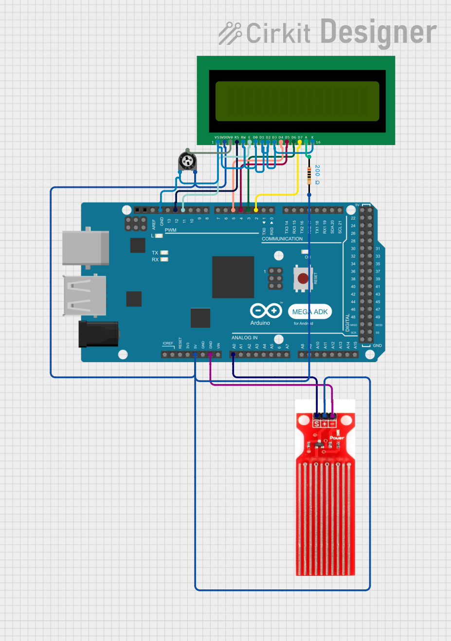
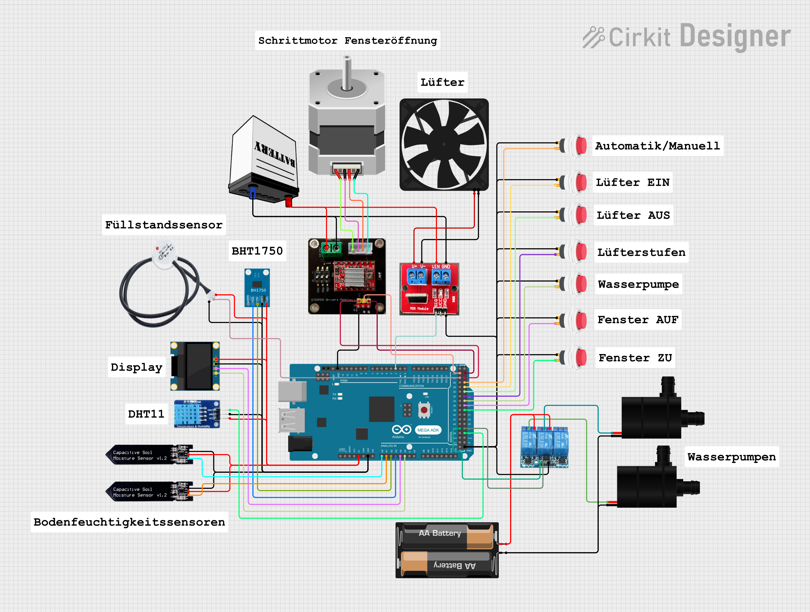
Explore Projects Built with AdaGator Side Black
Common Applications and Use Cases
- Wearable electronics
- Educational projects
- Rapid prototyping
- DIY crafts
- Interactive art installations
Technical Specifications
The AdaGator Side Black is designed to complement the Adafruit Gemma board and does not have electronic components that dictate voltage, current, or power ratings. However, it is crucial to adhere to the specifications of the Gemma board when using the AdaGator Side Black.
Pin Configuration and Descriptions
| Pin Label | Description |
|---|---|
| VOUT | Voltage output from Gemma, connected to external components |
| A1 | Analog input/output pin 1 |
| A2 | Analog input/output pin 2 |
| D0 | Digital input/output pin 0, also used for serial communication |
| D1 | Digital input/output pin 1, also used for I2C SDA |
| D2 | Digital input/output pin 2, also used for I2C SCL |
| GND | Ground connection |
Usage Instructions
How to Use the Component in a Circuit
- Connecting to Gemma: Align the AdaGator Side Black's connector with the Gemma board's side pins and gently press to make a secure connection.
- Prototyping: Use the labeled pins on the AdaGator Side Black to connect other electronic components such as sensors, LEDs, or actuators.
- Programming Gemma: Use the Arduino IDE or other compatible software to program the Gemma board. The AdaGator Side Black will route the signals accordingly.
Important Considerations and Best Practices
- Power Limits: Always check the power requirements of the components you are connecting to the AdaGator Side Black to avoid damaging the Gemma board.
- Secure Connections: Ensure that all connections are secure and that there is no risk of short circuits.
- Code Efficiency: When programming the Gemma board, write efficient code to optimize battery life, especially for wearable applications.
Troubleshooting and FAQs
Common Issues
- Loose Connections: If components are not responding as expected, check to ensure that all connections are secure.
- Incorrect Pin Usage: Double-check that the correct pins are being used for the intended purpose, as per the Gemma board's specifications.
Solutions and Tips for Troubleshooting
- Reconnect: Disconnect and reconnect the AdaGator Side Black to ensure a proper connection.
- Test Components Separately: Isolate and test each component individually to rule out any defective parts.
- Check Code: Verify that the code uploaded to the Gemma board is correct and that the correct pins are being addressed.
FAQs
Q: Can the AdaGator Side Black be used with other boards besides the Gemma? A: The AdaGator Side Black is specifically designed for the Adafruit Gemma board and may not be compatible with other boards.
Q: Is soldering required to use the AdaGator Side Black? A: No, the AdaGator Side Black is designed for easy prototyping and does not require soldering when used with the Gemma board.
Q: How do I power my project using the AdaGator Side Black? A: Power your project through the Gemma board, which can be powered via USB or a battery. The VOUT pin on the AdaGator Side Black will provide power to your connected components.
Example Code for Arduino UNO
// Example code for blinking an LED connected to the AdaGator Side Black
// and the Adafruit Gemma board.

#define LED_PIN 1 // Define the pin connected to the LED

void setup() {
  pinMode(LED_PIN, OUTPUT); // Set the LED pin as an output
}

void loop() {
  digitalWrite(LED_PIN, HIGH); // Turn the LED on
  delay(1000);                // Wait for a second
  digitalWrite(LED_PIN, LOW);  // Turn the LED off
  delay(1000);                // Wait for a second
}
Note: The example code provided is for illustrative purposes and is intended to be used with the Adafruit Gemma board programmed via the Arduino IDE or compatible software. Ensure that the LED is connected to the correct pin on the AdaGator Side Black corresponding to the Gemma board's pinout.