Cirkit Designer Logo
Cirkit Designer
Your all-in-one circuit design IDE
Home / 
Component Documentation

How to Use Servo (PWM/V/G): Examples, Pinouts, and Specs

Image of Servo (PWM/V/G)
Cirkit Designer LogoDesign with Servo (PWM/V/G) in Cirkit Designer

Introduction

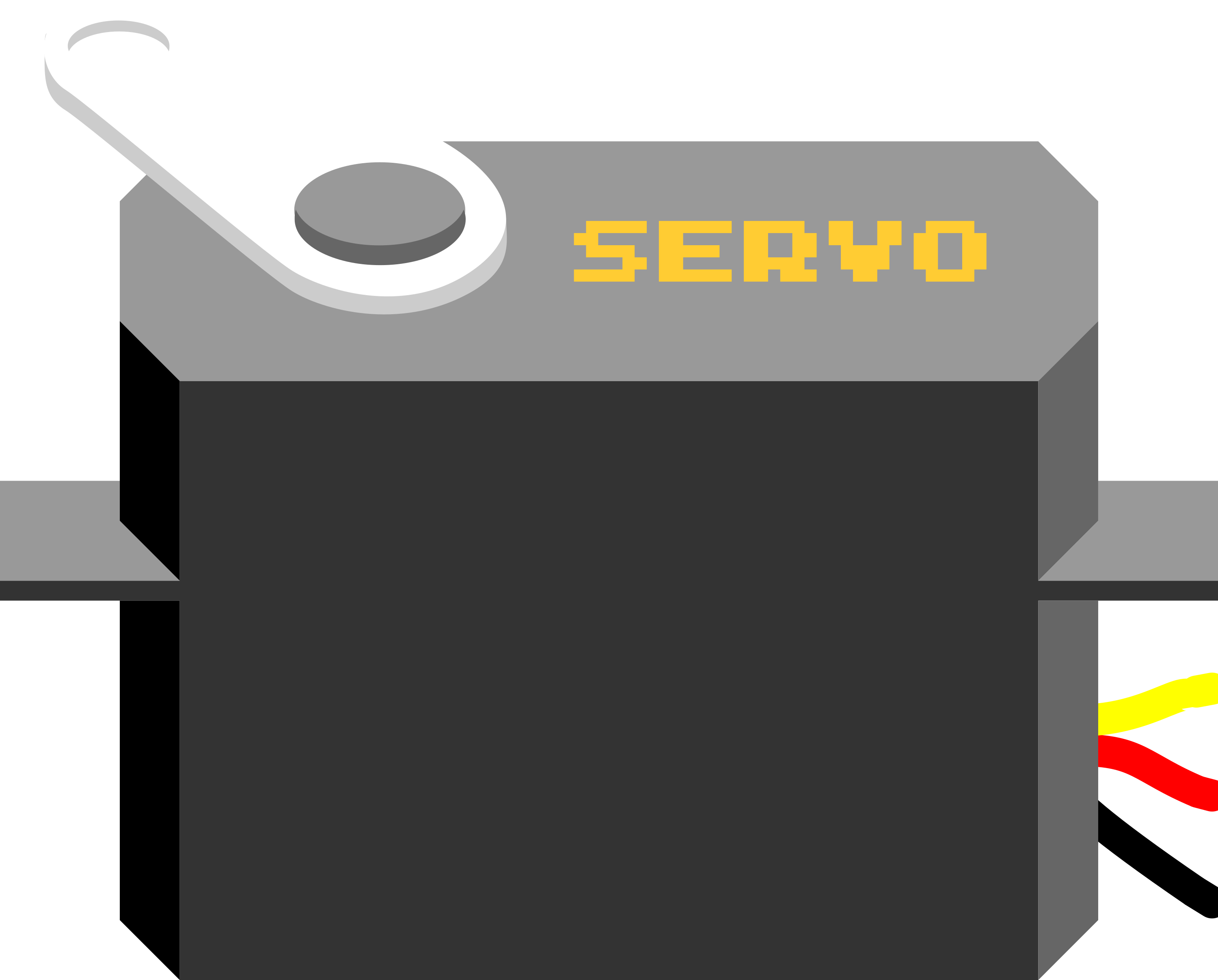
A servo motor is a compact and versatile electromechanical device designed for precise angular positioning. The Servo (PWM/V/G) operates using Pulse Width Modulation (PWM) signals, voltage (V), or current (G) signals to control its movement. It is widely used in robotics, automation, and hobbyist projects due to its reliability and ease of use.

Explore Projects Built with Servo (PWM/V/G)

Use Cirkit Designer to design, explore, and prototype these projects online. Some projects support real-time simulation. Click "Open Project" to start designing instantly!
Arduino Mega 2560 Controlled Servo Motor System
Image of project2: A project utilizing Servo (PWM/V/G) in a practical application
This circuit consists of an Arduino Mega 2560 microcontroller connected to a servo motor. The Arduino controls the servo motor via a PWM signal on pin D9, while providing power and ground connections to the servo motor from its 5V and GND pins, respectively.
Cirkit Designer LogoOpen Project in Cirkit Designer
Arduino Mega 2560 Controlled Multi-Servo Random Positioning System
Image of robotic: A project utilizing Servo (PWM/V/G) in a practical application
This circuit consists of an Arduino Mega 2560 microcontroller connected to twelve servo motors, each individually controlled by a distinct PWM pin on the Arduino. The servos are powered by a single Polymer Lithium Ion Battery, with all servos sharing a common power (VCC) and ground (GND) connection. The embedded code on the Arduino is designed to randomly position each servo within a 0 to 180-degree range, with a random delay between movements, demonstrating a multi-servo control system possibly for applications like robotics or animatronics.
Cirkit Designer LogoOpen Project in Cirkit Designer
Arduino UNO Controlled Multi-Servo System
Image of Robostride: A project utilizing Servo (PWM/V/G) in a practical application
This circuit consists of an Arduino UNO microcontroller controlling six servos, each connected to a separate digital pin (D4 to D9) for PWM signals. The servos are powered by a DC power source, with all GND and VCC pins properly connected to ensure stable operation. The provided Arduino code is a basic template with setup and loop functions, ready for further development.
Cirkit Designer LogoOpen Project in Cirkit Designer
Arduino UNO Controlled Servo Motor Sweeper
Image of servo motor: A project utilizing Servo (PWM/V/G) in a practical application
This circuit consists of an Arduino UNO microcontroller connected to a servo motor. The Arduino provides power to the servo and controls its position through a PWM signal on pin D9. The embedded code on the Arduino sweeps the servo motor back and forth between 0 and 180 degrees, which could be used for applications such as actuating a mechanical lever or controlling a small robotic arm.
Cirkit Designer LogoOpen Project in Cirkit Designer

Explore Projects Built with Servo (PWM/V/G)

Use Cirkit Designer to design, explore, and prototype these projects online. Some projects support real-time simulation. Click "Open Project" to start designing instantly!
Image of project2: A project utilizing Servo (PWM/V/G) in a practical application
Arduino Mega 2560 Controlled Servo Motor System
This circuit consists of an Arduino Mega 2560 microcontroller connected to a servo motor. The Arduino controls the servo motor via a PWM signal on pin D9, while providing power and ground connections to the servo motor from its 5V and GND pins, respectively.
Cirkit Designer LogoOpen Project in Cirkit Designer
Image of robotic: A project utilizing Servo (PWM/V/G) in a practical application
Arduino Mega 2560 Controlled Multi-Servo Random Positioning System
This circuit consists of an Arduino Mega 2560 microcontroller connected to twelve servo motors, each individually controlled by a distinct PWM pin on the Arduino. The servos are powered by a single Polymer Lithium Ion Battery, with all servos sharing a common power (VCC) and ground (GND) connection. The embedded code on the Arduino is designed to randomly position each servo within a 0 to 180-degree range, with a random delay between movements, demonstrating a multi-servo control system possibly for applications like robotics or animatronics.
Cirkit Designer LogoOpen Project in Cirkit Designer
Image of Robostride: A project utilizing Servo (PWM/V/G) in a practical application
Arduino UNO Controlled Multi-Servo System
This circuit consists of an Arduino UNO microcontroller controlling six servos, each connected to a separate digital pin (D4 to D9) for PWM signals. The servos are powered by a DC power source, with all GND and VCC pins properly connected to ensure stable operation. The provided Arduino code is a basic template with setup and loop functions, ready for further development.
Cirkit Designer LogoOpen Project in Cirkit Designer
Image of servo motor: A project utilizing Servo (PWM/V/G) in a practical application
Arduino UNO Controlled Servo Motor Sweeper
This circuit consists of an Arduino UNO microcontroller connected to a servo motor. The Arduino provides power to the servo and controls its position through a PWM signal on pin D9. The embedded code on the Arduino sweeps the servo motor back and forth between 0 and 180 degrees, which could be used for applications such as actuating a mechanical lever or controlling a small robotic arm.
Cirkit Designer LogoOpen Project in Cirkit Designer

Common Applications

  • Robotic arms and grippers
  • RC vehicles (cars, boats, planes)
  • Automated camera gimbals
  • Industrial automation systems
  • DIY electronics and Arduino projects

Technical Specifications

Key Technical Details

Parameter Value
Operating Voltage 4.8V to 6.0V
Stall Torque 1.5 kg·cm to 2.5 kg·cm (varies by model)
Operating Speed 0.1 to 0.2 seconds per 60° (at 6V)
Control Signal PWM (Pulse Width Modulation)
PWM Frequency 50 Hz
PWM Duty Cycle Range 1 ms (0°) to 2 ms (180°)
Idle Current ~10 mA
Maximum Current ~1 A (under load)
Angular Range 0° to 180°
Connector Type 3-pin (PWM, V, G)

Pin Configuration

The Servo (PWM/V/G) has a standard 3-pin connector. Below is the pinout description:

Pin Number Pin Name Description
1 PWM Signal pin for PWM control
2 V Positive voltage supply (4.8V–6.0V)
3 G Ground (0V)

Usage Instructions

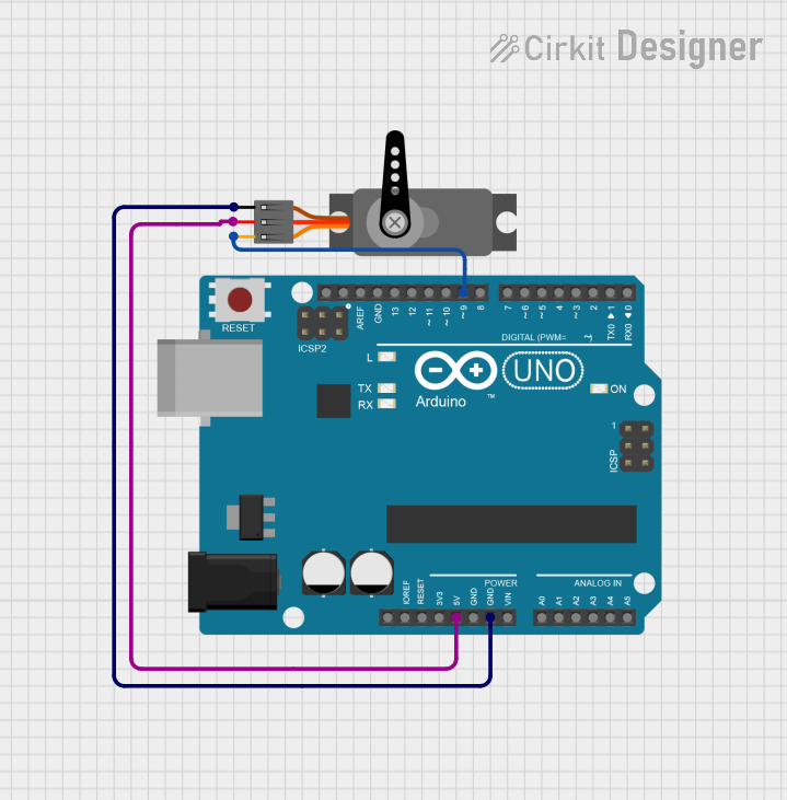
How to Use the Servo in a Circuit

  1. Power Supply: Connect the V pin to a 5V or 6V power source and the G pin to ground. Ensure the power supply can handle the servo's current requirements, especially under load.
  2. PWM Signal: Connect the PWM pin to a microcontroller or PWM signal generator. The PWM signal controls the servo's angular position:
    • A 1 ms pulse corresponds to 0°.
    • A 1.5 ms pulse corresponds to 90° (neutral position).
    • A 2 ms pulse corresponds to 180°.
  3. Load Considerations: Avoid overloading the servo beyond its torque rating to prevent overheating or damage.

Best Practices

  • Use a dedicated power supply for the servo to avoid voltage drops that could affect other components.
  • Add a decoupling capacitor (e.g., 100 µF) across the power supply to stabilize voltage.
  • Avoid sending PWM signals outside the specified range (1 ms to 2 ms) to prevent mechanical strain.

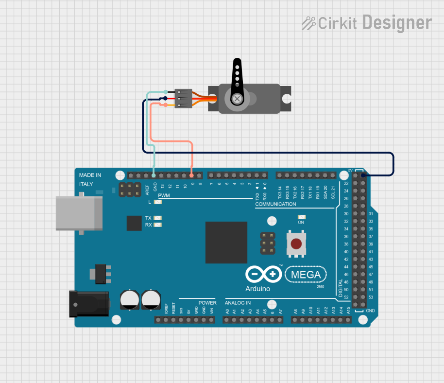
Example: Connecting to an Arduino UNO

Below is an example of how to control the Servo (PWM/V/G) using an Arduino UNO:

#include <Servo.h> // Include the Servo library

Servo myServo; // Create a Servo object

void setup() {
  myServo.attach(9); // Attach the servo to pin 9 on the Arduino
}

void loop() {
  myServo.write(0); // Move servo to 0 degrees
  delay(1000);      // Wait for 1 second

  myServo.write(90); // Move servo to 90 degrees
  delay(1000);       // Wait for 1 second

  myServo.write(180); // Move servo to 180 degrees
  delay(1000);        // Wait for 1 second
}

Notes:

  • Ensure the servo is connected to a pin capable of PWM output (e.g., pin 9 on Arduino UNO).
  • Use an external power source if the servo draws more current than the Arduino can supply.

Troubleshooting and FAQs

Common Issues and Solutions

  1. Servo Not Moving

    • Cause: Incorrect wiring or insufficient power supply.
    • Solution: Double-check the connections and ensure the power supply meets the servo's voltage and current requirements.
  2. Servo Jittering

    • Cause: Electrical noise or unstable PWM signal.
    • Solution: Add a decoupling capacitor across the power supply and ensure the PWM signal is stable.
  3. Servo Overheating

    • Cause: Overloading the servo or continuous operation at high torque.
    • Solution: Reduce the load on the servo or allow it to rest periodically.
  4. Limited Angular Movement

    • Cause: PWM signal out of range or mechanical obstruction.
    • Solution: Verify the PWM signal is within the 1 ms to 2 ms range and check for physical obstructions.

FAQs

Q: Can I power the servo directly from the Arduino?
A: While possible for small servos, it is not recommended for larger servos due to current limitations. Use an external power supply.

Q: What happens if I send a PWM signal outside the specified range?
A: The servo may attempt to move beyond its mechanical limits, potentially causing damage.

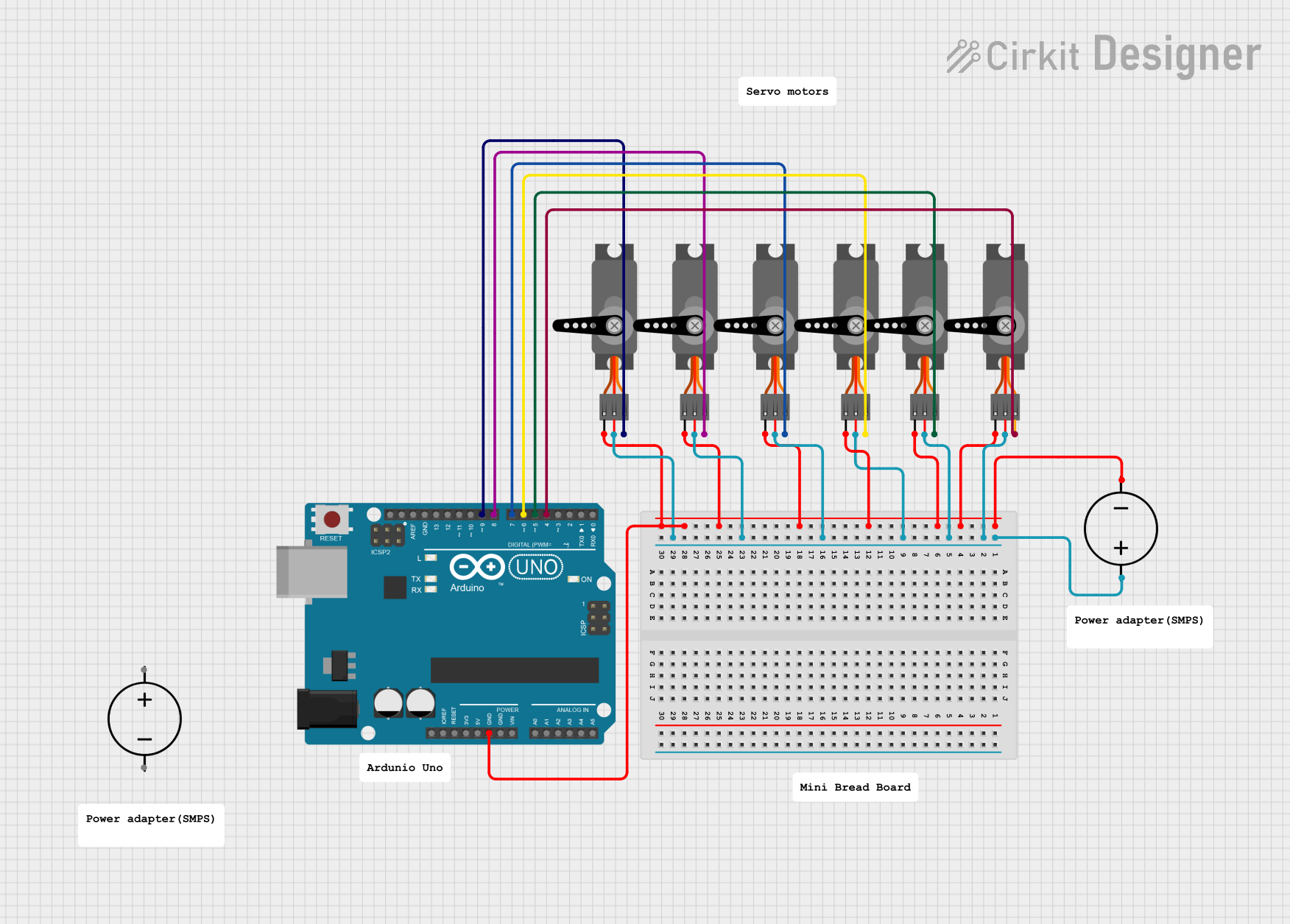
Q: Can I control multiple servos with one Arduino?
A: Yes, you can control multiple servos using different PWM-capable pins. Use the Servo library to manage multiple servos efficiently.

Q: How do I know if my servo is compatible with my project?
A: Check the servo's voltage, torque, and speed specifications to ensure they meet your project's requirements.