
How to Use ATmega328 (DIP-28): Examples, Pinouts, and Specs
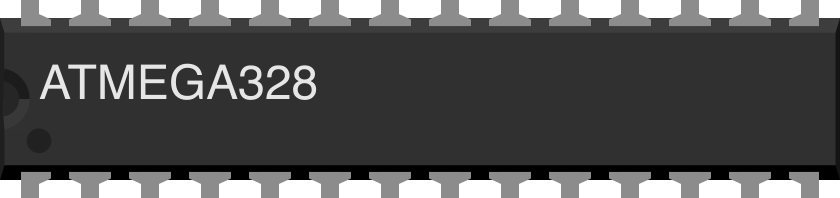
 Design with ATmega328 (DIP-28) in Cirkit Designer
Introduction
The ATmega328 is a low-power, high-performance 8-bit microcontroller developed by Microchip (formerly Atmel). It is based on the AVR RISC architecture and is widely used in embedded systems, IoT devices, and hobbyist projects. The ATmega328 is particularly popular due to its integration in Arduino boards, such as the Arduino UNO.
Key features of the ATmega328 include 32 KB of flash memory, 2 KB of SRAM, 1 KB of EEPROM, and 23 general-purpose I/O pins. Its compact DIP-28 package makes it easy to use in breadboard and prototyping applications.
Explore Projects Built with ATmega328 (DIP-28)
 Open Project in Cirkit Designer
 Open Project in Cirkit Designer
 Open Project in Cirkit Designer
 Open Project in Cirkit Designer
Explore Projects Built with ATmega328 (DIP-28)
Open Project in Cirkit DesignerOpen Project in Cirkit DesignerOpen Project in Cirkit DesignerOpen Project in Cirkit DesignerCommon Applications
- Arduino-based projects
- Home automation systems
- Robotics and motor control
- Sensor interfacing and data logging
- IoT devices and wearable electronics
Technical Specifications
Key Specifications
| Parameter | Value |
|---|---|
| Architecture | 8-bit AVR RISC |
| Operating Voltage | 1.8V - 5.5V |
| Flash Memory | 32 KB |
| SRAM | 2 KB |
| EEPROM | 1 KB |
| Clock Speed | Up to 20 MHz |
| I/O Pins | 23 |
| ADC Channels | 6 (10-bit resolution) |
| Timers | 3 (2x 8-bit, 1x 16-bit) |
| Communication Interfaces | UART, SPI, I²C (TWI) |
| Package | DIP-28 |
Pin Configuration
The ATmega328 in the DIP-28 package has 28 pins, each with specific functions. Below is the pinout description:
| Pin No. | Pin Name | Function Description |
|---|---|---|
| 1 | PC6 (RESET) | Reset input (active low) |
| 2 | PD0 (RXD) | UART Receive (Serial Communication) |
| 3 | PD1 (TXD) | UART Transmit (Serial Communication) |
| 4 | PD2 | Digital I/O, External Interrupt 0 (INT0) |
| 5 | PD3 | Digital I/O, External Interrupt 1 (INT1) |
| 6 | PD4 | Digital I/O |
| 7 | VCC | Power Supply (2.7V - 5.5V) |
| 8 | GND | Ground |
| 9 | PB6 (XTAL1) | External Oscillator Input |
| 10 | PB7 (XTAL2) | External Oscillator Output |
| 11 | PD5 | Digital I/O |
| 12 | PD6 | Digital I/O, PWM Output |
| 13 | PD7 | Digital I/O |
| 14 | PB0 | Digital I/O, PWM Output |
| 15 | PB1 | Digital I/O, PWM Output |
| 16 | PB2 | Digital I/O, PWM Output |
| 17 | PB3 | Digital I/O, SPI MOSI |
| 18 | PB4 | Digital I/O, SPI MISO |
| 19 | PB5 | Digital I/O, SPI SCK |
| 20 | AVCC | Analog Power Supply |
| 21 | AREF | Analog Reference Voltage |
| 22 | GND | Ground |
| 23 | PC0 (ADC0) | Analog Input Channel 0 |
| 24 | PC1 (ADC1) | Analog Input Channel 1 |
| 25 | PC2 (ADC2) | Analog Input Channel 2 |
| 26 | PC3 (ADC3) | Analog Input Channel 3 |
| 27 | PC4 (ADC4) | Analog Input Channel 4, I²C SDA |
| 28 | PC5 (ADC5) | Analog Input Channel 5, I²C SCL |
Usage Instructions
Using the ATmega328 in a Circuit
- Power Supply: Connect the VCC pin to a regulated power source (2.7V to 5.5V) and the GND pin to ground. For analog functionality, connect AVCC to the same voltage as VCC and AREF to the desired reference voltage.
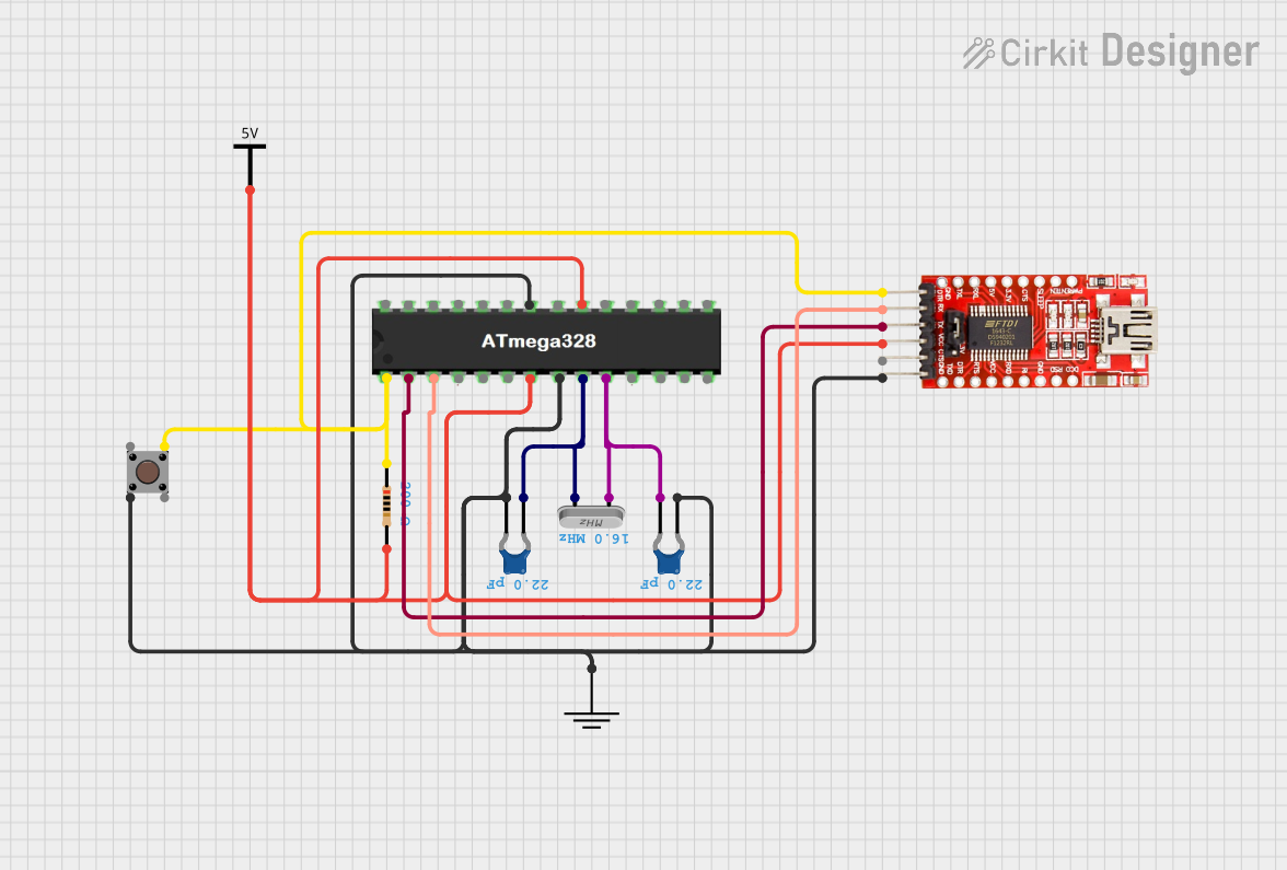
- Clock Source: Use an external 16 MHz crystal oscillator connected to XTAL1 and XTAL2, along with two 22 pF capacitors to ground, for stable operation.
- Reset: Connect a 10 kΩ pull-up resistor to the RESET pin to ensure proper startup.
- Programming: Use an ISP (In-System Programmer) or an Arduino as an ISP to upload code to the ATmega328.
Example: Blinking an LED with Arduino UNO
The ATmega328 is the microcontroller used in the Arduino UNO. Below is an example code to blink an LED connected to pin 13:
// Blink an LED connected to digital pin 13
void setup() {
  pinMode(13, OUTPUT); // Set pin 13 as an output
}

void loop() {
  digitalWrite(13, HIGH); // Turn the LED on
  delay(1000);            // Wait for 1 second
  digitalWrite(13, LOW);  // Turn the LED off
  delay(1000);            // Wait for 1 second
}
Best Practices
- Decouple the power supply with 0.1 µF and 10 µF capacitors near the VCC and AVCC pins.
- Avoid leaving unused pins floating; connect them to ground or configure them as outputs.
- Use a proper bootloader (e.g., Arduino bootloader) for easier programming.
Troubleshooting and FAQs
Common Issues
Microcontroller Not Responding
- Cause: Incorrect power supply or missing decoupling capacitors.
- Solution: Verify the power connections and add decoupling capacitors.
Program Upload Fails
- Cause: Incorrect ISP connections or missing bootloader.
- Solution: Check the ISP wiring and ensure the bootloader is installed.
Analog Readings Are Inaccurate
- Cause: AREF pin not connected or noisy power supply.
- Solution: Connect AREF to a stable reference voltage and use proper decoupling.
External Oscillator Not Working
- Cause: Incorrect crystal or capacitor values.
- Solution: Use a 16 MHz crystal with 22 pF capacitors.
FAQs
Q: Can I use the ATmega328 without an external crystal?
A: Yes, the ATmega328 has an internal 8 MHz oscillator, but it is less accurate than an external crystal.
Q: How do I reset the ATmega328?
A: Pull the RESET pin low momentarily to reset the microcontroller.
Q: What is the maximum current per I/O pin?
A: Each I/O pin can source or sink up to 40 mA, but it is recommended to limit it to 20 mA for safe operation.
Q: Can I use the ATmega328 with 3.3V systems?
A: Yes, the ATmega328 operates at 3.3V, but ensure the clock speed does not exceed 12 MHz at this voltage.
This concludes the documentation for the ATmega328 (DIP-28).